
Aluminum intercooler prototypes
An intercooler prototype combines a finned core with end sections, ports and mounting interfaces. The quotation separates machining from core supply and joining, and identifies the assembly-fit checks and requested tests.
Made to your drawing. The approved specification defines dimensions, material, finish and the supplied components.
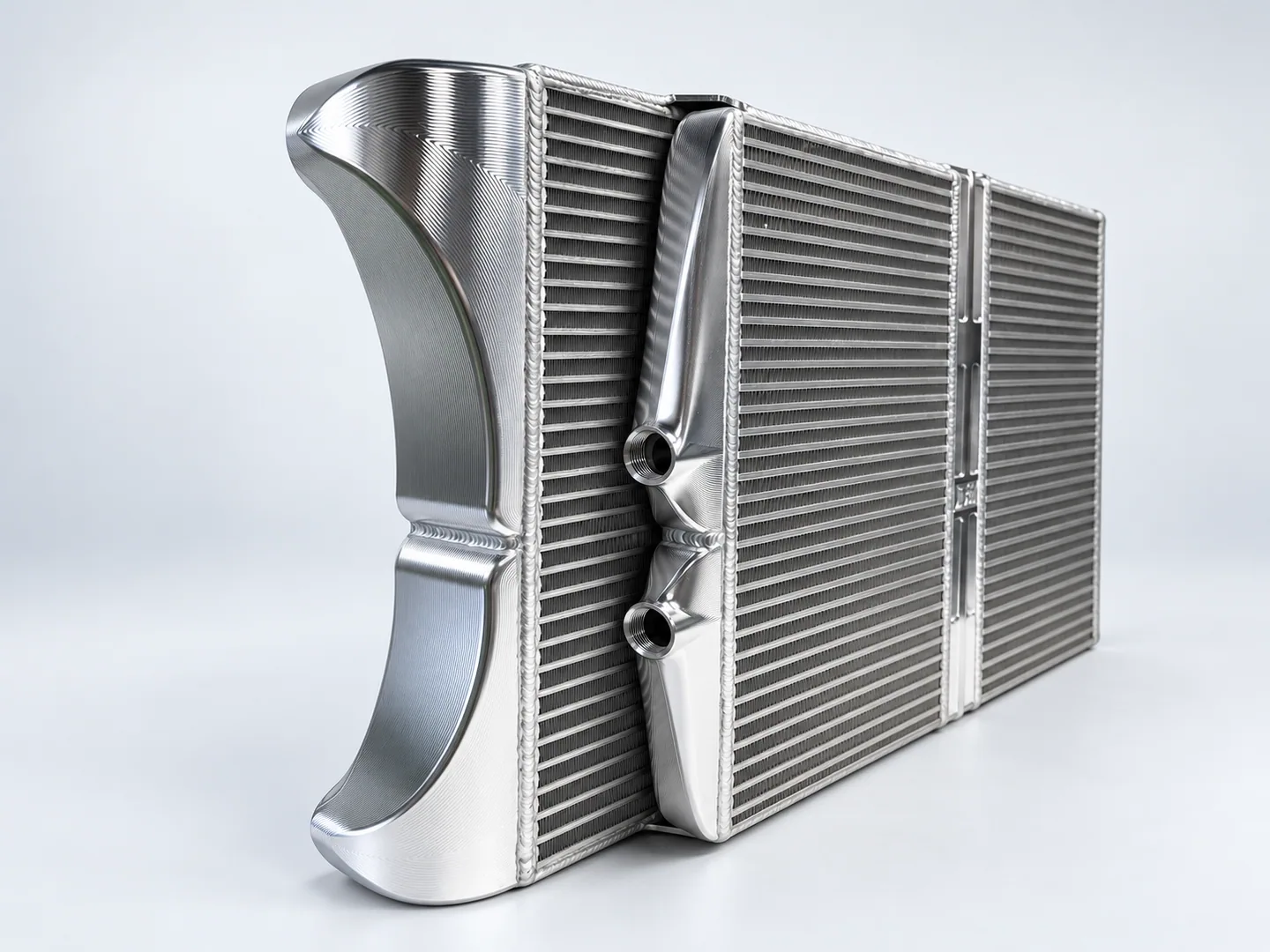
The core, end sections and machined connections
We review the core specification separately from the machined ports and mounting surfaces. The assembly envelope and joining details show which components and operations belong in the quotation.
Define the machined, purchased and customer-supplied items, joining and fasteners in the assembly model. Agree the supplied scope and acceptance after assembly.
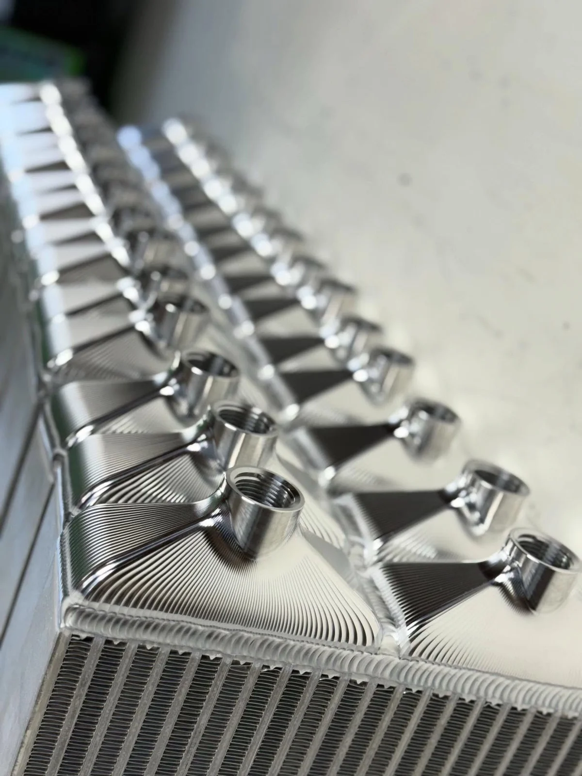
End sections and repeated fins. Specify the assembly components and required cooling tests in the order.
| Feature | Drawing requirements | Acceptance checks |
|---|---|---|
| Core, end tanks and supplied components | Show the core, end tanks, ports and brackets in one assembly model. Identify customer-supplied items and each component material; one alloy may not suit the entire assembly. Distinguish CNC machining, TIG joining and separately supplied components in the quotation. | Component materials and supplied-item scope. |
| Mounting & port orientation | Define port orientation relative to the core. Mark mounting and port dimensions for acceptance after joining, with the vehicle packaging and fitment clear in the model. | Mounting and port dimensions after joining; any pressure-test criteria agreed separately. |
| Functional tests & acceptance | Specify any required pressure, leak, flow or cooling tests separately from machining. Include the assembly condition, test pressure and medium where relevant, procedure and acceptance limits. The quotation identifies test availability and responsibility, including any vehicle-specific validation. | For pressure or leak testing, supply test pressure, medium, procedure and acceptance criteria. |
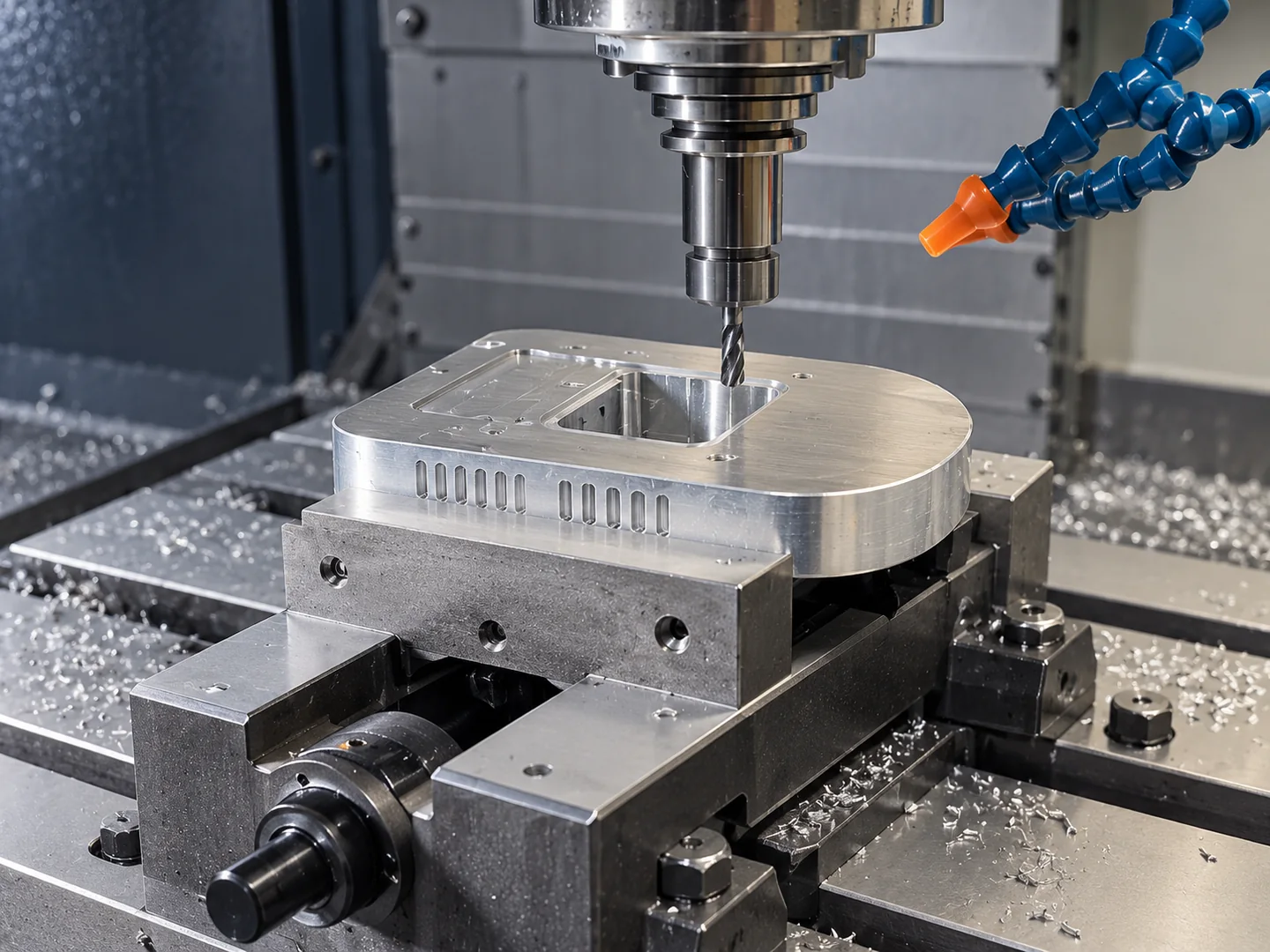
Machined interfaces within a joined assembly
Connection faces and mounting features may be machined before or after joining. The assembly model must define the supplied core, access to each interface and the final datums used for inspection.
For prototype acceptance, specify fit checks and any pressure, leak or cooling test. Include the assembly condition, procedure and acceptance limits for each test.
Each component needs a locating and machining plan across its setups. CNC machining and TIG joining are separate scopes in the order.
Related machining and part forms
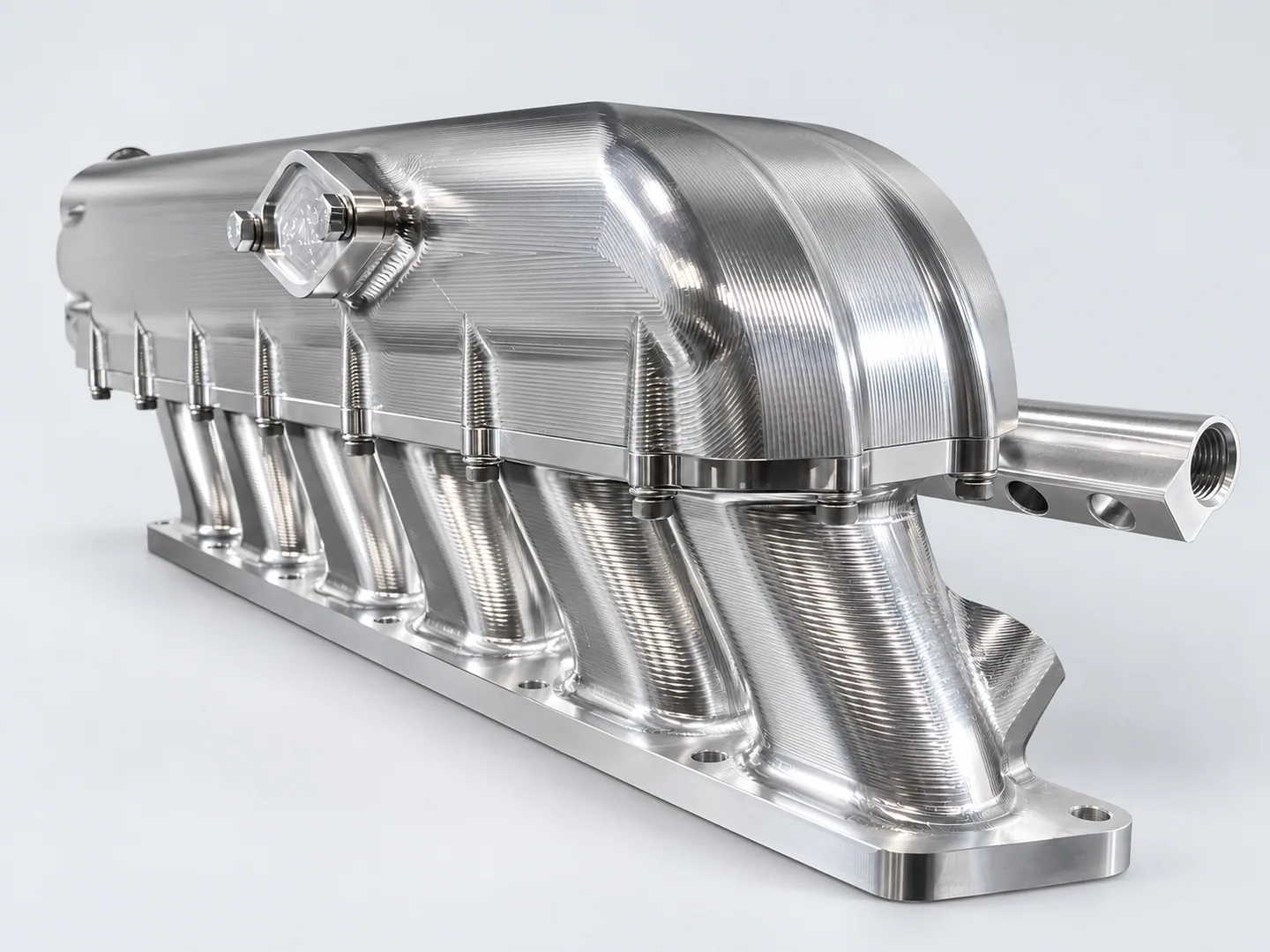
Billet aluminum intake plenums
Intake plenums require an internal chamber and connection geometry. An intercooler also needs a core specification and a joining plan.
Request a quote for your part
- Assembly definitionAssembly model and controlled revision, each component material, supplied-core details and joining responsibilities.
- Validation & orderIntended validation plan, quantity and delivery destination. Define test responsibilities and acceptance conditions separately.
Tell us how the part will be accepted, including measurement methods, its condition at inspection, sampling and report format.