

5-Axis CNC Machining Services
LZZ operates 8 five-axis machines in Hangzhou for multi-face components, angled features and curved geometries, from prototypes to small production runs.
ISO 9001 certifiedMade to your drawing · Hangzhou, China
Five-axis machining
at LZZ
Our five-axis machines reach angled faces, pockets and curved surfaces on multi-face components. Rotary workholding positions the part beneath the spindle in our workshop.
- Five-axis machines
- 8
- Critical dimensions
- ±0.005 mmOn reviewed features, subject to part evaluation
- Dimensional inspection
- CMMFeature and datum checks to the drawing
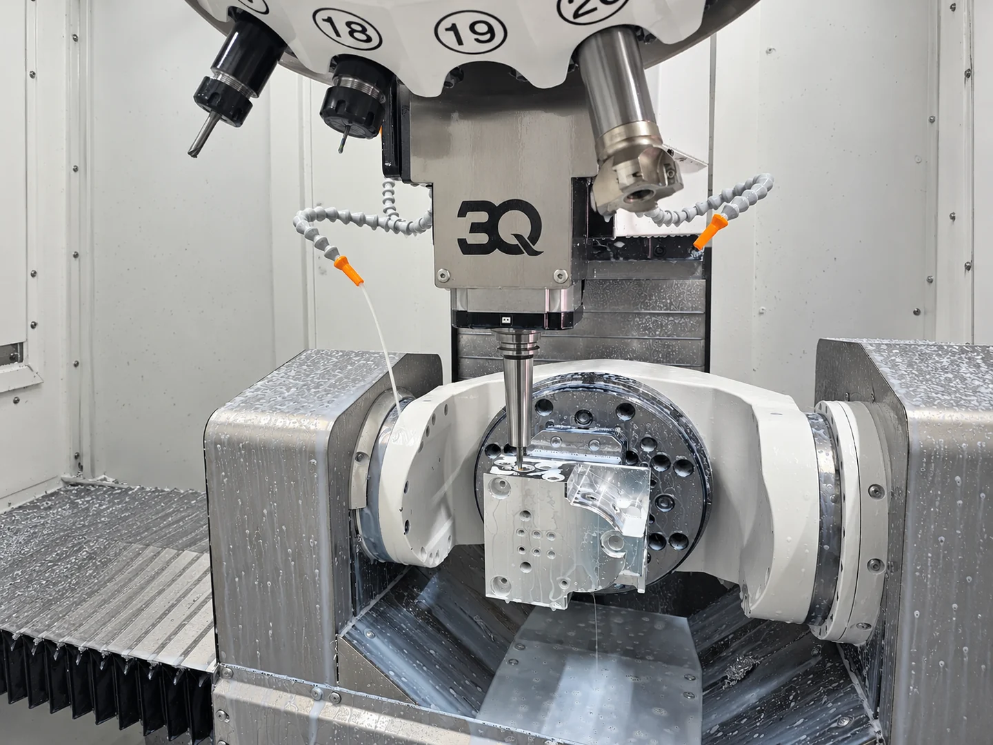
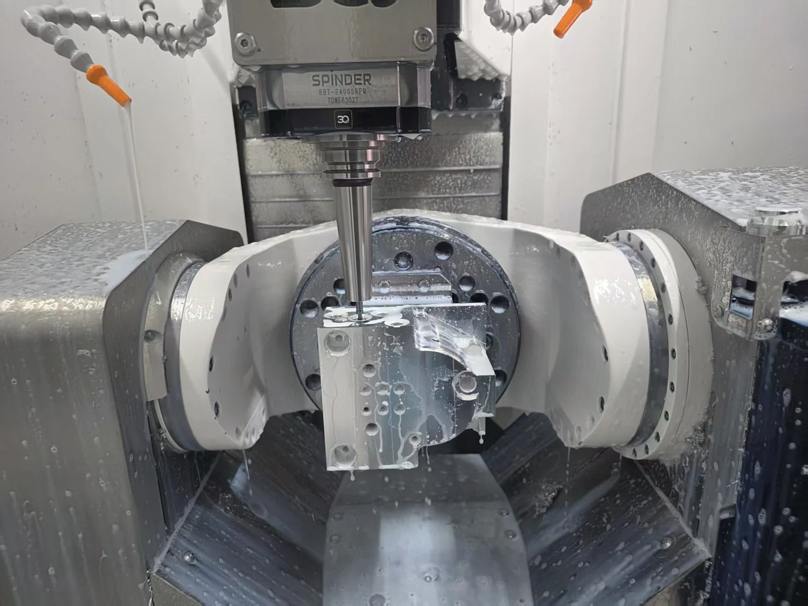
Machined parts &
complex geometries
Finished components from our workshop and related part shapes for discussing your design.
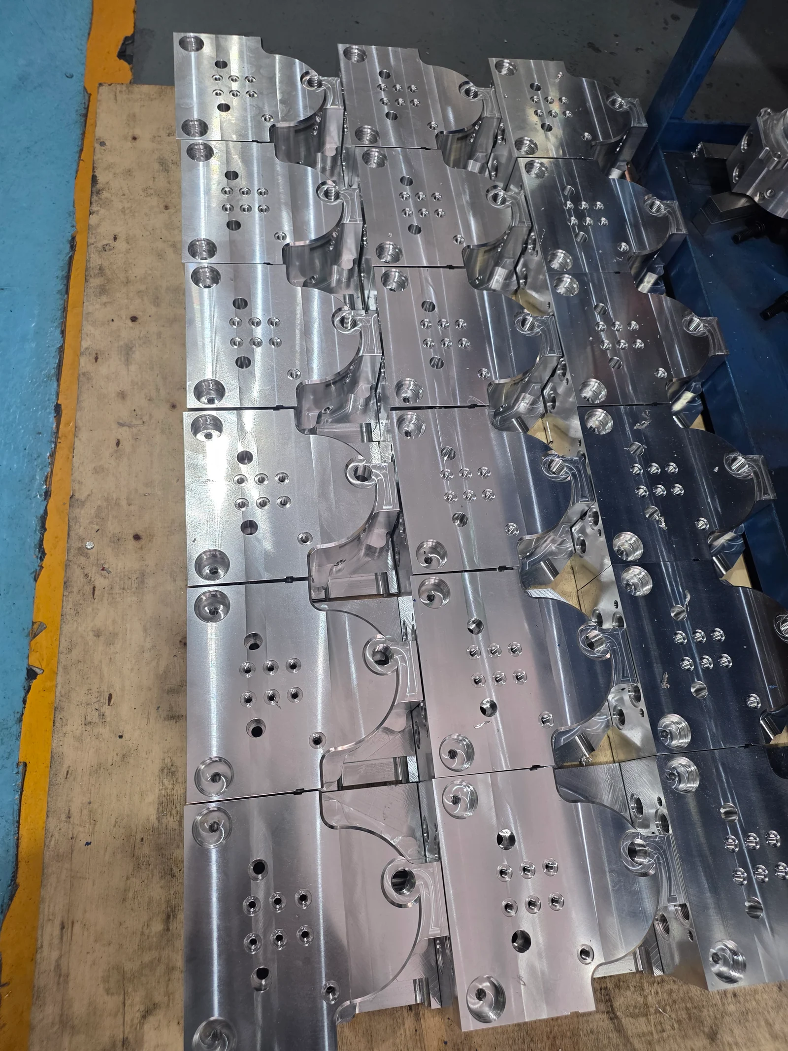
Bores, holes and working faces reached from different directions need a common datum scheme. The drawing sets their positional and profile requirements.
Related part references
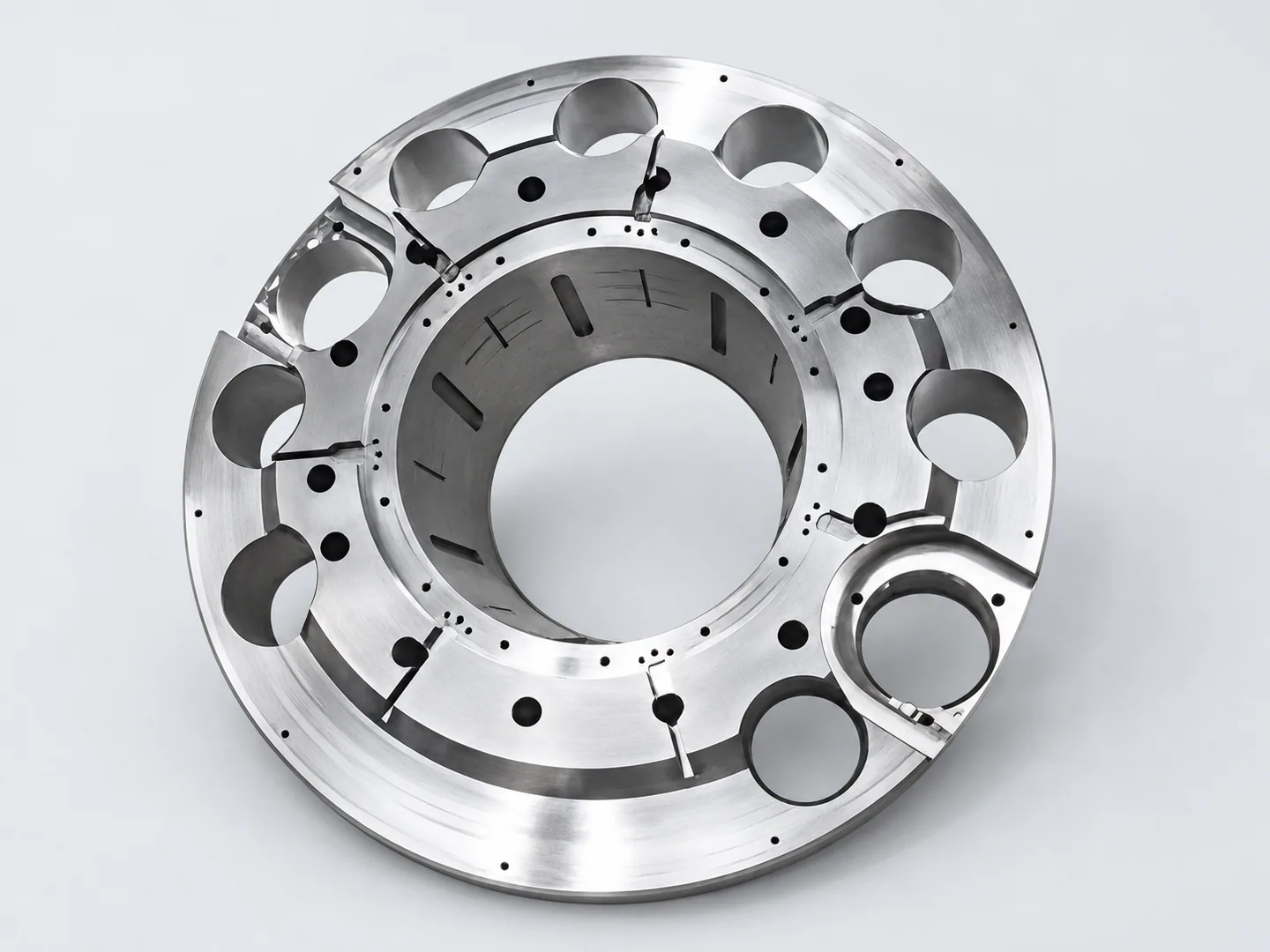
Multi-bore circular milled component
Contours and angled faces requiring access from several directions.
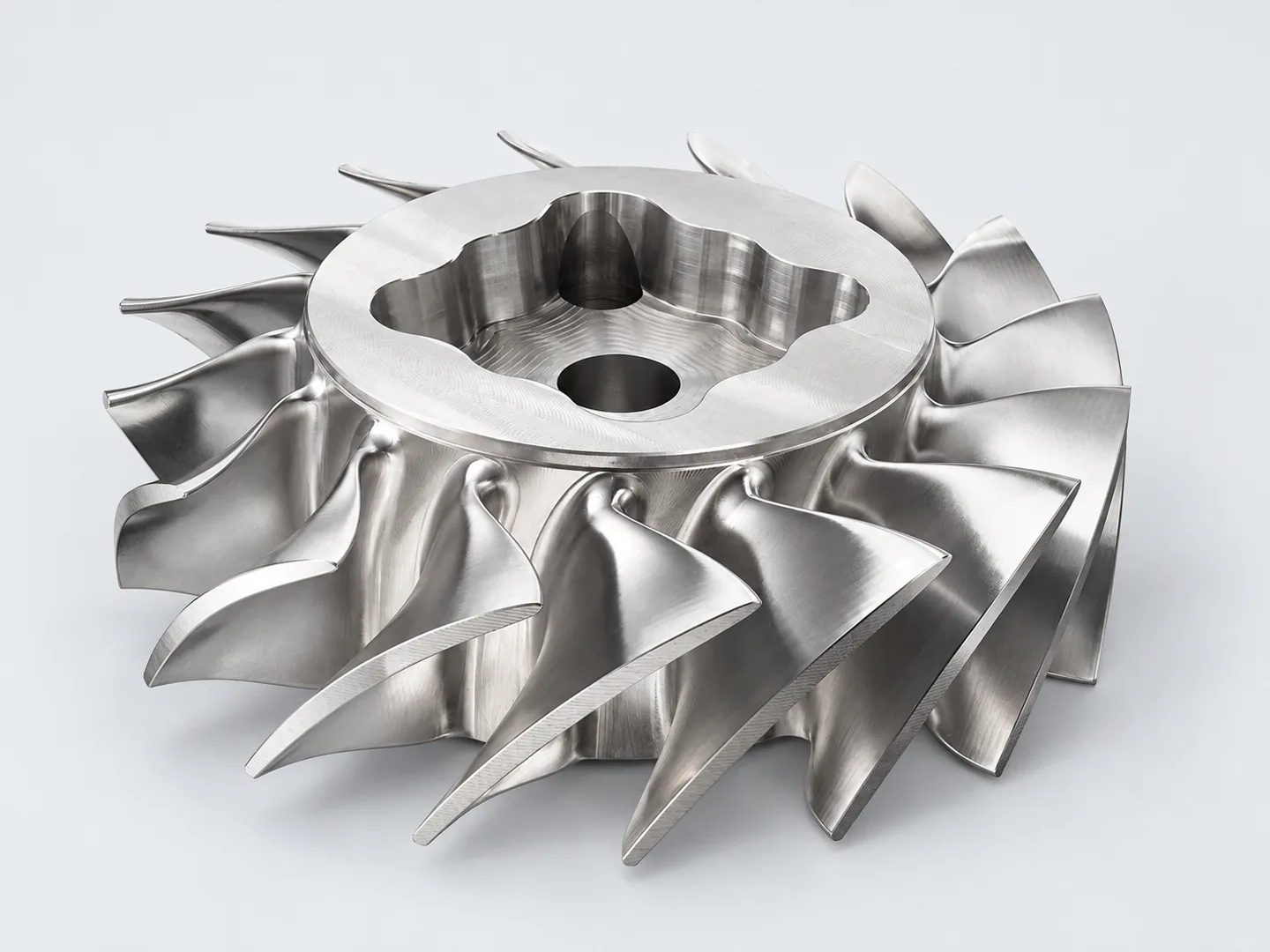
Turbine & fluid-system components
Blades and hubs with curved surfaces. Specify functional tests separately.
Match the tool path to the surface
An angled hole or face may be reached with the part held at a fixed orientation. A continuous curved surface may require the tool direction to change along its path. Both routes depend on cutter reach and clearance around the workpiece and fixture.
- Indexed positioning
- The rotary axes hold a selected orientation while the tool cuts an angled face. A shared datum scheme relates features on different faces.
- Simultaneous motion
- The tool orientation changes along a continuous contour. We review the model, tool reach and fixture clearance to determine whether the part needs this motion.
Size and workholding
Tool reach, fixture clearance and protected surfaces in each orientation.
We assess machine travel, load and fixture clearance from the finished and blank dimensions, weight and any surfaces that cannot be clamped.
When changing the tool direction helps
Some features need a different fixed tool approach. Others need the tool direction to change during cutting. The surface geometry determines which type of multi-axis work is appropriate.
- A few accessible faces in different directions
- Several setups or indexed positioning
- If each feature can be cut at a fixed orientation, continuous five-axis motion may add little. Compare access and datum transfer before choosing the route.
- Several angled faces or difficult side access
- A multi-axis positioning review
- Reorienting the part can improve access around it. Fixture, tool and spindle clearance still limit what can be reached in each position.
- A continuous curved or blade-like surface
- Whether orientation must change along the cut
- The model may call for simultaneous motion to follow the contour. Surface shape, tool reach and clearance need to be checked before that route is confirmed.
Material and finish review
Alongside tool access, we review the exact alloy, hardness or treatment condition, stock removal and required final surface. These details determine the machining sequence.
| Material / scope | Specification | Finish / treatment | Confirm for this drawing |
|---|---|---|---|
| Aluminum | Specify alloy, temper and stock form. | Machined surfaces or a specified compatible finish. | Protect thin sections and define post-treatment interfaces. |
| Titanium | Specify grade and condition. | Surface texture and edge requirements to the drawing. | Identify tool access, thin sections and material records. |
| Nickel alloys | For an Inconel part, specify the exact alloy and stock condition for review. | Agree the final surface and any treatment separately. | Include stock condition, traceability and acceptance criteria. |
| Stainless steel | Specify grade, hardness or heat-treatment condition. | Machined surfaces or a treatment suitable for the selected grade. | Confirm the machining and inspection sequence around treatment. |
Measure against the model and datums
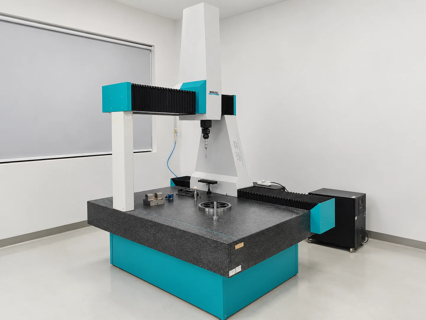
We measure profiles and positions from the drawing datums. The inspection plan names the features, any surfaces compared with the model and the results to record.
| Feature | Specify on the drawing | Agree before production |
|---|---|---|
| Profiles & contours | Current 3D model revision, datum scheme, surface profile and permitted tool marks. | Measurement method, surfaces compared with the model and recorded profile results. |
| Features across faces | Hole and bore axes, mounting interfaces and relative positions. | Locating method and recorded position results for features reached across faces. |
| Thin sections & clearance | Wall sections, blank dimensions, weight and protected clamping areas. | Review tool access and handling; agree balance, leak or other functional tests separately. |
| Traceability & final end use | Identify final end use, applicable export requirements and the required material or part traceability. | Traceability documents and acceptance records for the controlled model revision. |
Requirements for the application
- Robotics & automation
- Show mounting interfaces, sensor or bracket locations, assembly clearances and access requirements. State any suitability or approval requirements for the equipment.
- Industrial fans & impellers
- Blade hubs and rotating forms need space for the cutter and fixtures, with material and inspection suited to the drawing.
- Aerospace & defense equipment
- Include the drawing, traceability requirements, final end use and applicable export requirements for the proposed component.
Any sector-specific qualification or testing needs to be specified and agreed for the order.
Request a 5-axis machining quote
- Current native or neutral 3D model and controlled drawing revision
- Finished and blank dimensions, weight, clamping areas and protected surfaces
- Assembly clearances, mating-part envelope and tool / fixture access
- Material grade and condition, finish, critical features and validation criteria
- Traceability, final end use and applicable export requirements
- Quantity, delivery destination and requested date