
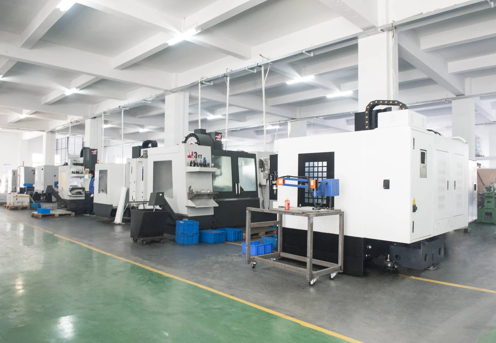
CNC factory & quality control
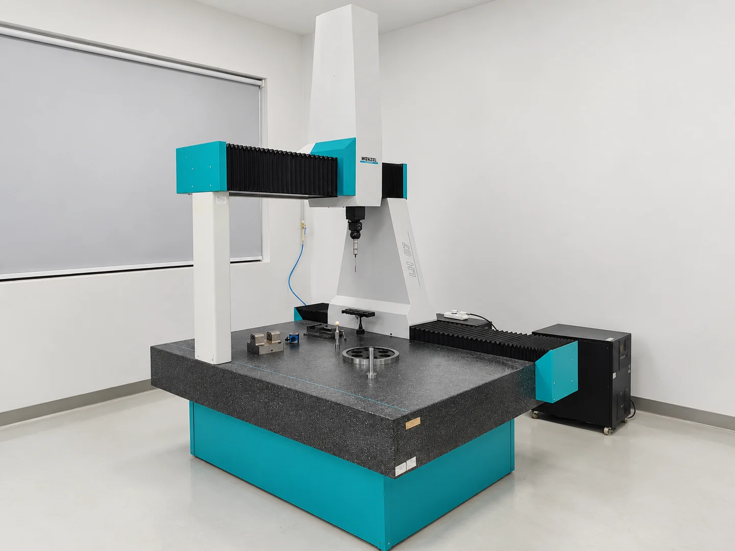
8 five-axis machines and 10 CNC lathes in our 1,500 m² Hangzhou workshop, with CMM inspection for custom machined parts.
ISO 9001 certifiedMade to your drawing · Hangzhou, China
- 5-axis machines
- 8
- CNC lathes
- 10
- Production facility
- 1,500 m²
- Critical dimensions
- ±0.005 mmSubject to part evaluation
Equipment & machining capacity
Five-axis machining, CNC turning and milling support prototypes and small production runs. The equipment total includes machining and supporting units.
| Facility / capability | Capacity & scope |
|---|---|
| Production facility | 1,500 m²Hangzhou, China |
| Equipment total | 40+ unitsMachining and supporting equipment combined |
| 5-axis machines | 8 machinesFor multi-face and contoured components |
| CNC lathes | 10 machinesFor shafts, sleeves, fittings and rotational parts |
| Tolerance reference | ±0.01 mmDrawing- and feature-dependent |
| Critical dimensions | ±0.005 mmOn reviewed features, subject to part evaluation |
| Part size & workholding | Reviewed per drawingFinished and blank dimensions, weight and fixture clearance |
| Inspection equipment | CMM, height gauges and optical measurementMethods and report scope agreed for the order |
| Reference monthly output | About 100,000 small partsVaries with size, geometry, material, finishing and order mix |
Machines, machining and parts
Workshop photographs and machining records from LZZ.
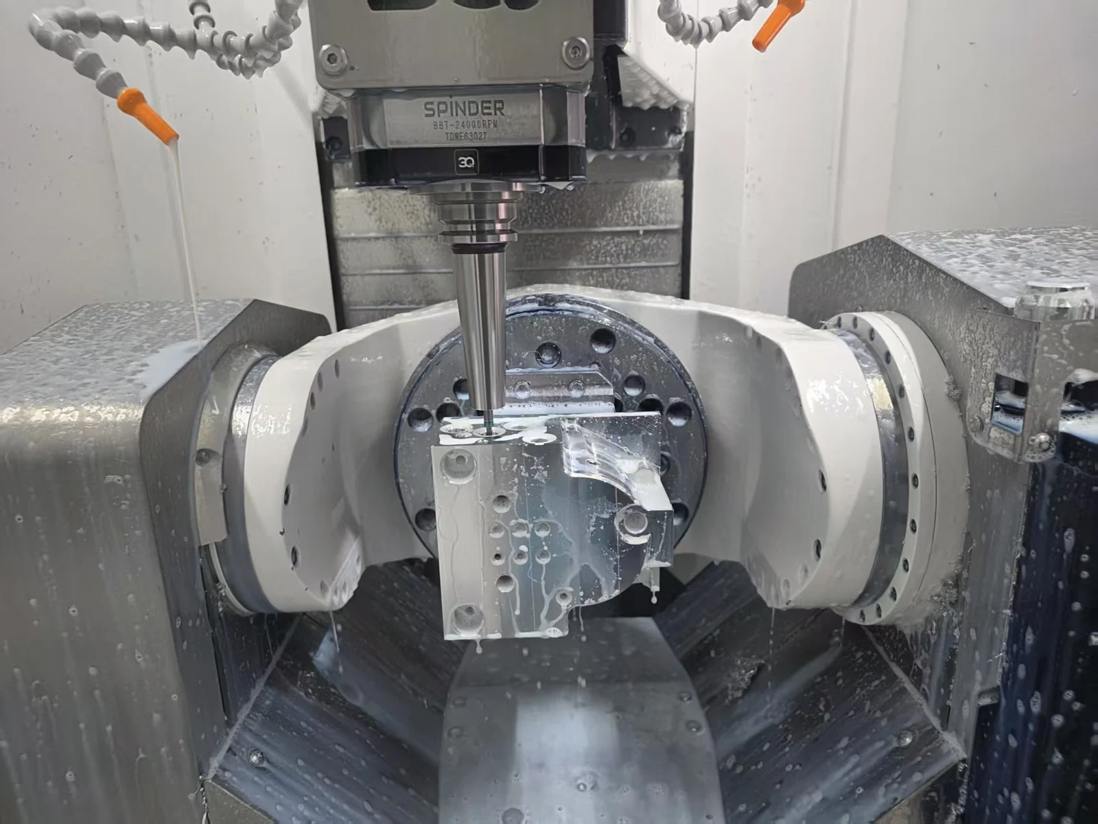
5-axis machining
Eight machines for angled features, pockets and geometry reached from several directions.
View the multi-face machining record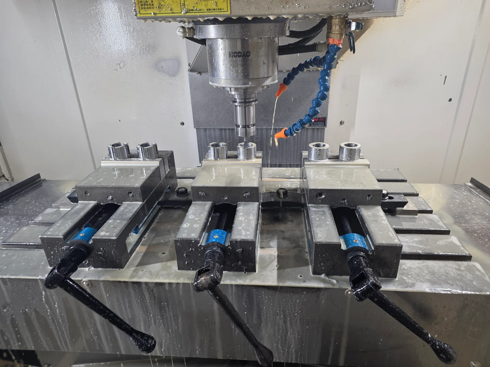
CNC turning and milling
Ten CNC lathes support rotational parts. Secondary milling adds holes, slots and off-axis features.
View the turning and milling record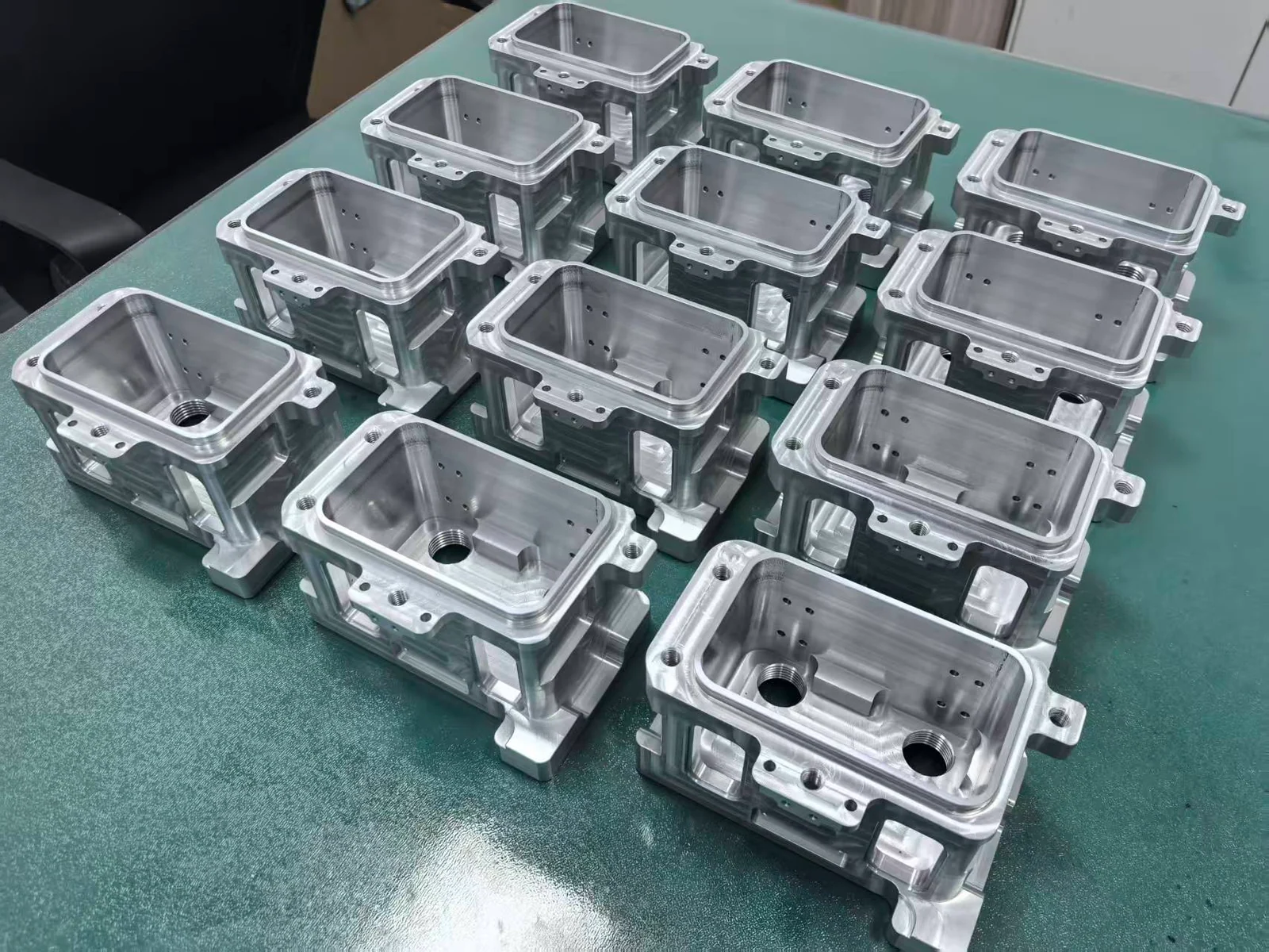
Aluminum housings
Machined cavities, bores and mounting features in a group of aluminum housings.
View a display-housing machining recordMachining routes, setup and part fit
We plan the setup around cutter access and clamping, preserving the required relationships between features.
| Machining route | Common parts | Geometry and workholding | Related examples |
|---|---|---|---|
| CNC milling | Housings, instrument blocks and brackets. | Pocket depth, internal corner radii and thin walls affect cutter access and support. Mounting faces and bores need a consistent datum through each setup. | |
| CNC turning and turn-mill | Shafts, sleeves, fittings and flanges. | Diameters and shoulders are located from the part axis. Slender sections need support; cross-holes, flats and off-axis features need tool access and an angular reference. | |
| Multi-axis machining | Multi-face components and contoured parts. | Tool orientation, holder clearance and fixture position determine access around the part. Features across faces need shared datums; the model shows whether cutting requires a fixed or changing tool angle. |
Indexed positioning and simultaneous five-axis cutting
With indexed positioning, the rotary axes set a fixed angle before cutting. The cutter then machines that face with the rotary axes held in position. Simultaneous five-axis cutting coordinates linear and rotary motion during the cut, changing the tool angle along the surface.
We review tool access and workholding from your model, then confirm the proposed machining route and its limits in the quotation. If the part requires simultaneous five-axis cutting, that route needs confirmation before ordering.
More about multi-axis part geometryInspection from drawing to finished parts
We base inspection on the drawing’s critical features and datums. Before production, we agree acceptance limits, sampling, approval hold points and the records needed to release the parts.
Drawing review
We use the drawing revision to identify critical features and inspection datums. We record the limits, measurement methods and reporting requirements in the inspection plan.
First article
The initial part is checked before the production run. The order states whether your sample approval is a production hold point.
In-process checks
Specified features are checked during machining. The inspection plan sets check points, sampling and the handling of deviations.
Final inspection
Finished parts are checked against the agreed drawing and order. The inspection plan identifies checks before or after finishing and the final release records.
Incoming-material review establishes the required grade, condition, supplied blanks and material records. Any additional checks belong in the quotation.
Mark critical features on the drawingA measurement method for each feature
We locate the part from its drawing datums and use consistent support during measurement. The order specifies whether acceptance applies before or after finishing.
- Positions & geometric features
- Coordinate measuring machine (CMM)
Drawing datums, feature limits, support and measurement strategy.
- Heights & linear dimensions
- Height gauges
The reference surface, setup and accessible features.
- Suitable profiles
- Optical projectors
The profile, reference and measurement orientation.
- Threads, surface finish & special tests
- Method set in the quotation
Required thread, roughness, coating-thickness or hardness checks and records.
For supplier qualification, you can request instrument ranges and current calibration evidence relevant to the specified features. We agree the methods and records for additional special tests in the quotation.
Inspection records and supplier documents
We list the documents supplied with your parts in the quotation. Each record identifies the drawing revision and part or batch. You can also request equipment, capacity or inspection documents for supplier qualification.
Records for your parts
- Dimensional & first-article reports
- Measured features, datums, limits, methods and results. Drawing revision, part or batch reference, sampling and review details.
- Material records
- Grade, condition and the traceability needed for the part. Document type and availability confirmed in the quotation.
- Finishing documents
- Finishing process, special tests and required records. Part or batch reference and any checks after treatment.
- Surface & batch checks
- Cosmetic faces, masking, edges and sampling. Acceptance criteria and who approves any deviation.
Packing and handover
The packing plan covers surface protection, part identification and the records travelling with the order. The quotation sets delivery responsibilities.
- Protection for sealing faces, threads, cosmetic surfaces and vulnerable features.
- Part number, drawing revision and quantity identified on each pack.
- The specified dimensional, material and finishing records.
- Packing arrangements, shipment documents, destination and delivery responsibilities.
We agree the packing arrangement before shipment, including any customer review needed for the order.
Ask about your part
Leave your name, destination country and the best way to reach you. You can add a message or drawing, and mention any supplier documents your team needs.
Useful details when you have them
- A STEP model and 2D drawing with the part number, units and revision; which file controls if their requirements differ
- Material grade and condition, finish, quantity and surfaces that need protection
- Critical features, datums, tolerances and acceptance limits
- Any first-article approval, sampling, measurement methods and reports your order needs
- Delivery destination, requested date, packing and handover requirements
We send a first reply within 12 hours of receiving your inquiry. A complete quote may need further discussion of the drawing or process.
How we handle your projectYou can order from 1 piece. Production takes 7-14 business days after drawing and order confirmation, including finishing. Shipping takes additional time. Your quotation confirms the schedule for the quantity and requirements agreed.