
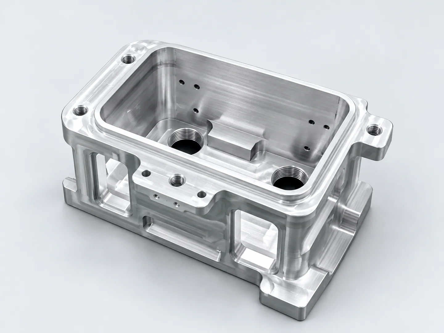
Pocketed aluminum housings
Pocketed bodies with bores and mounting interfaces. Specify any lid, gasket and sealing-face requirements on the drawing.
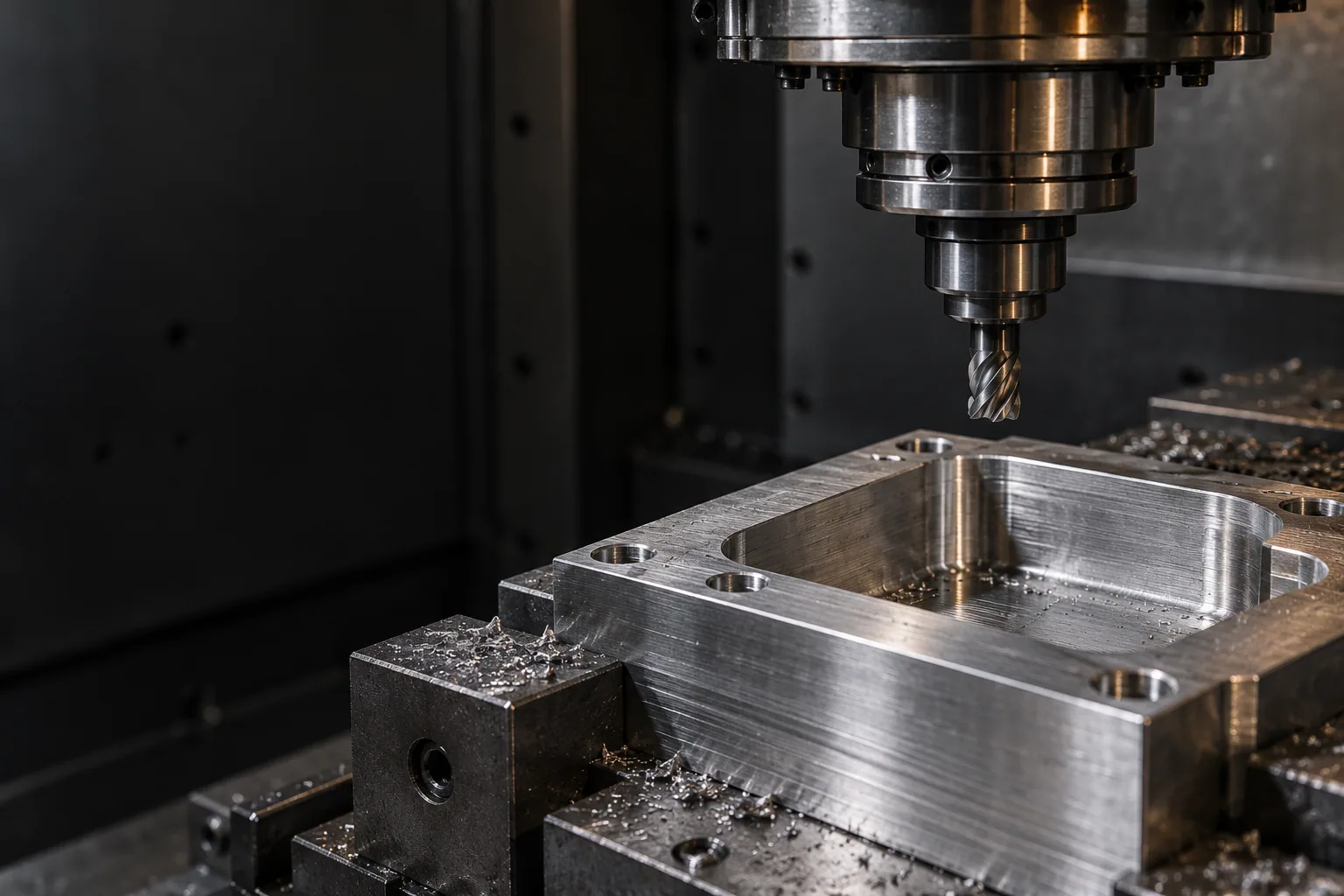
We mill housings, brackets and other custom parts with pockets, flat faces and hole patterns. Internal corners, wall thickness and the direction of each feature determine the tools and setups needed.
ISO 9001 certifiedMade to your drawing · Hangzhou, China
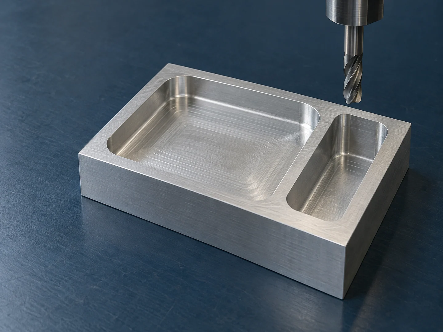
Deep pockets and small internal corners restrict the cutter and can require a more slender tool. Thin walls need support during cutting. To reach another face, we may reposition the part using locating surfaces that preserve the dimensional references.
Part and stock dimensions, clamping faces and tool clearance. Usable size depends on the fixture.
The surfaces that fit together establish the machining references. Their orientation and accessibility determine where we can hold the part and approach it with a cutter.
No. A part may use a three-axis setup, several setups or indexed positioning. The feature directions, contour and fixture clearance determine the route.
Milling leaves a radius at an internal corner. Specify the required corner geometry and any permitted radius so we can review the tool access and machining route.
Top-face and side-face features can need different holding positions. When a drawing requires repositioning, we locate the next setup from the first machined surfaces to preserve the dimensional relationships.
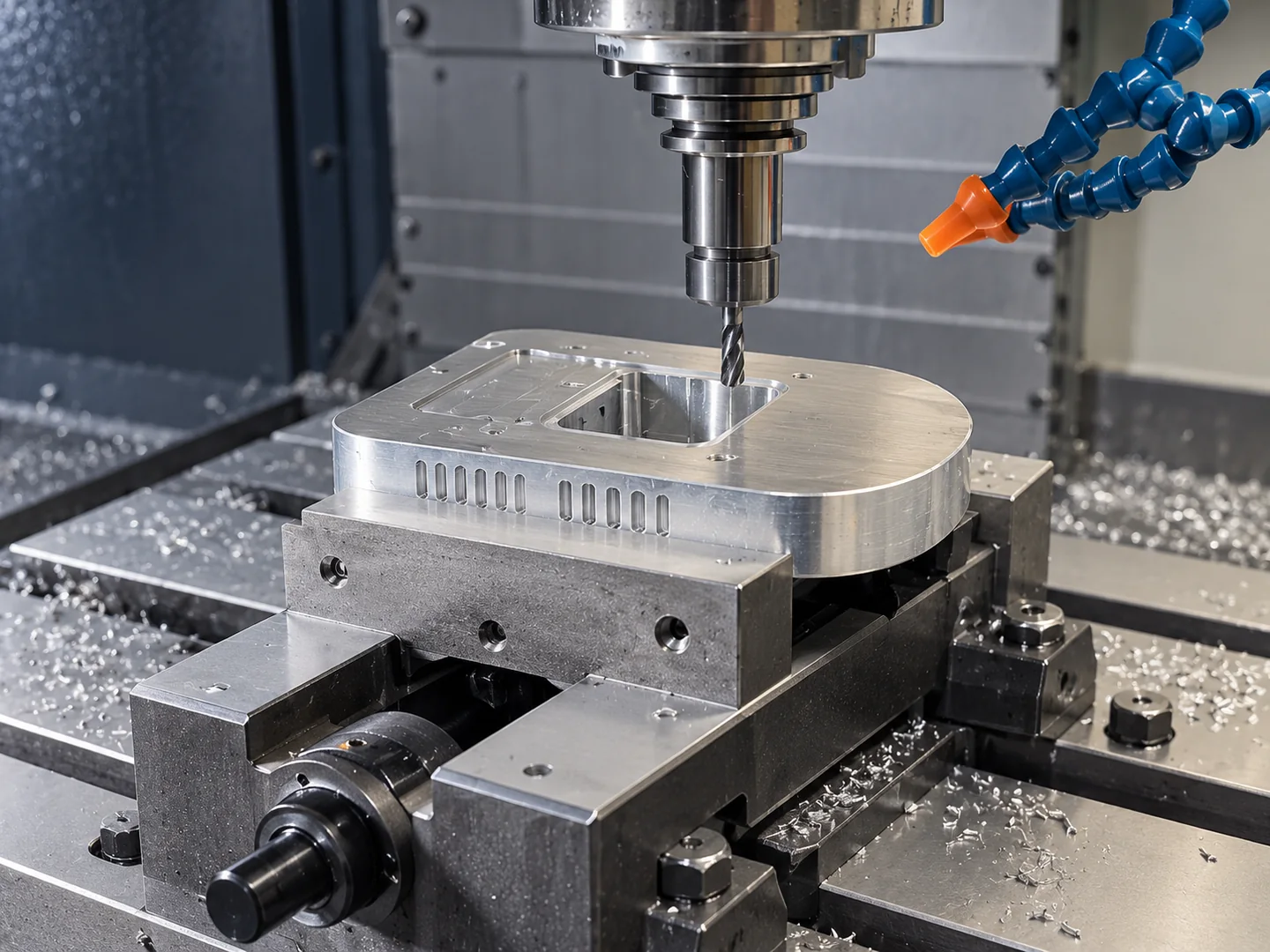
Choose stock and clamping faces so the initial pockets, bores and datum surfaces remain accessible.
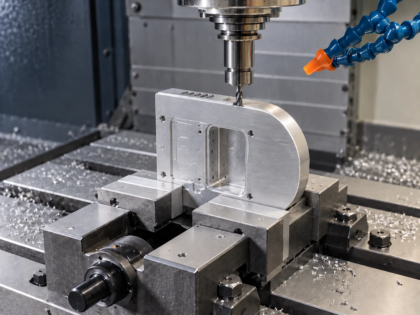
Use defined locating features when turning the workpiece to machine another face.
Aluminum can suit housings where weight matters. Steel, stainless steel, copper alloys and polymers suit different service conditions and need different cutting and workholding plans. We review the exact grade and treatment for the part, including fitted dimensions in their final specified condition.
| Material & specification | Finish / treatment | Part-specific requirements |
|---|---|---|
| Aluminum Specify alloy and temper; examples include 6061 and 7075. | Deburring, polishing, bead blasting or anodizing. | Mark protected fits and dimensions that apply after treatment. |
| Steel & stainless steel Specify the exact grade, stock condition and any heat treatment. | Machined surfaces, polishing or a compatible protective treatment. | Identify working interfaces, burr limits and required material records. |
| Copper & brass Specify the alloy and standard for contacts or fittings. | Polishing or compatible plating. | Define contact areas, threads and post-plating dimensions. |
| Engineering plastics Specify polymer grade, fillers and stock condition. | Machined surfaces with agreed edge quality and cleaning. | Include application conditions and the measurement state. |
For titanium parts, include the grade and condition so we can review tooling, finishing and availability.
Material and finish checklistSelected critical features±0.01 mm
We review selected critical features at ±0.01 mm. The accepted tolerance for each feature depends on the drawing, material, geometry, setup and measurement method.
| Feature | Drawing requirements | Inspection plan before production |
|---|---|---|
| Faces & mounting holes | Assembly datums, mounting faces, hole positions, bore fits and relationships between faces. | Measurement methods and recorded dimensions and positions referenced to the specified datums. |
| Pockets & thin walls | Pocket depths, minimum walls, internal radii, permitted tool access and any allowed radius or geometry changes. | Review distortion, tool marks and the limits required at critical sections. |
| Finish & protected areas | Finish, masking, cosmetic faces and dimensions that apply before or after treatment. | Acceptance stage and required finishing records, with separate procedures for cleanliness, chemical-contact or ESD tests. |
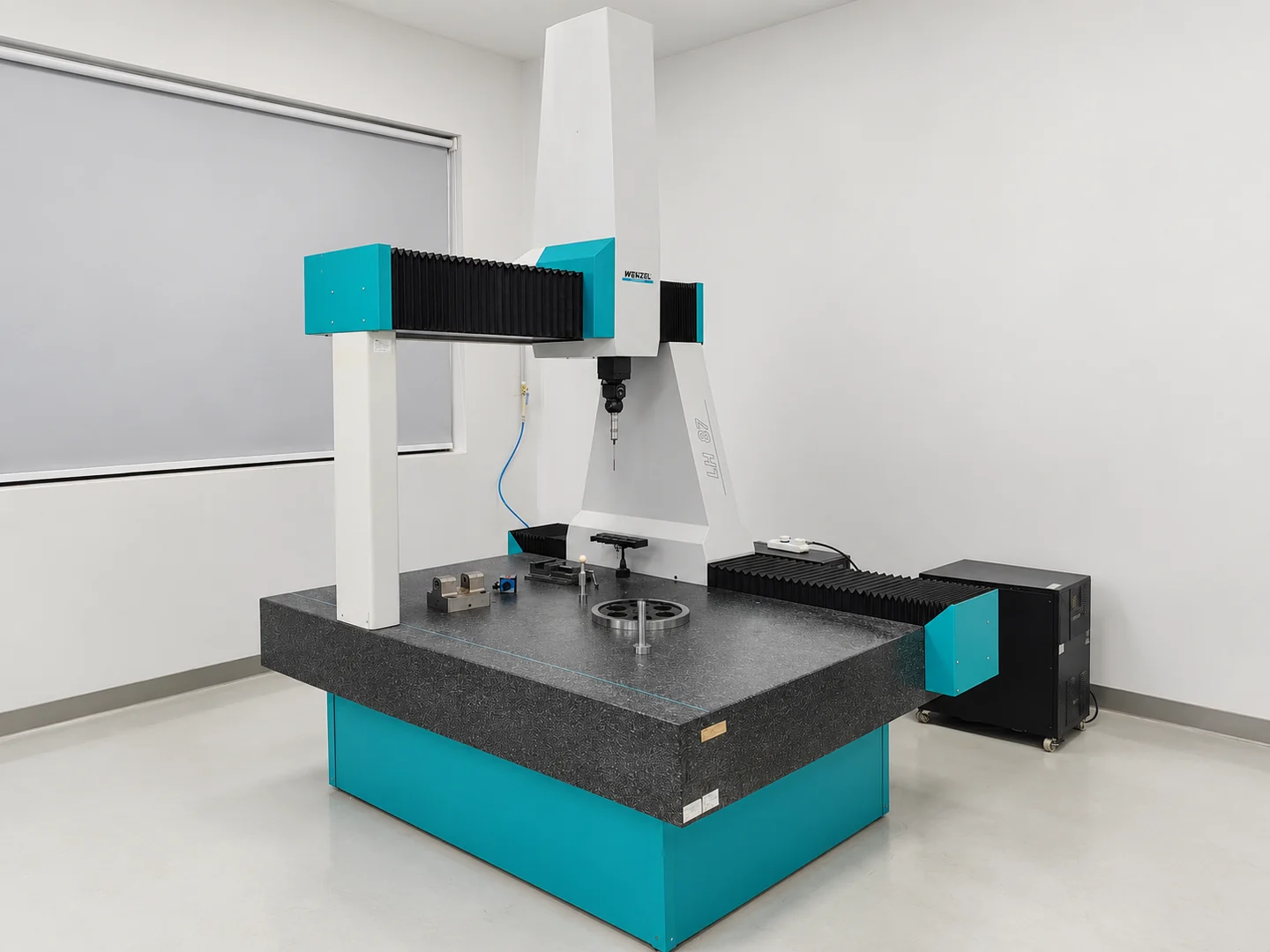
Any sector-specific qualification or testing needs to be specified and agreed for the order.
Blocks, brackets and housings combine flat faces, pockets and holes. Their datums and tool access determine the setup sequence.
Pocketed bodies with bores and mounting interfaces. Specify any lid, gasket and sealing-face requirements on the drawing.
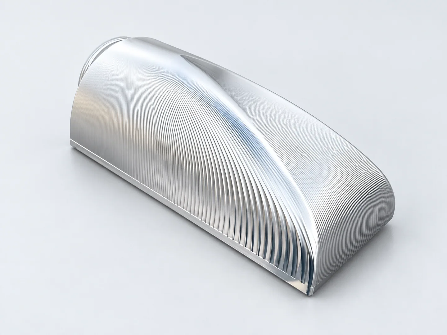
A contoured cover with interfaces for assembly checks.
If your specification is ready, include the details below. You can also start with a question.
Current 3D model and drawing, part number, units and revision.
Material grade, stock condition and stock dimensions.
Mating features, datums, holes, thin walls and permitted geometry or radius changes.
Protected surfaces, known clamping or access restrictions, and intended assembly or operating conditions.
Finish, masking, post-treatment acceptance and any required tests or records.
Quantity, delivery destination and requested date.