
Machined intake-system components
An intake-system component must connect at the correct positions and clear the surrounding engine hardware. Its assembly model supplies the flange geometry, fastener access and installation space needed to plan machining.
List the machined parts, bought-in items, joining and assembly work included in the quotation.
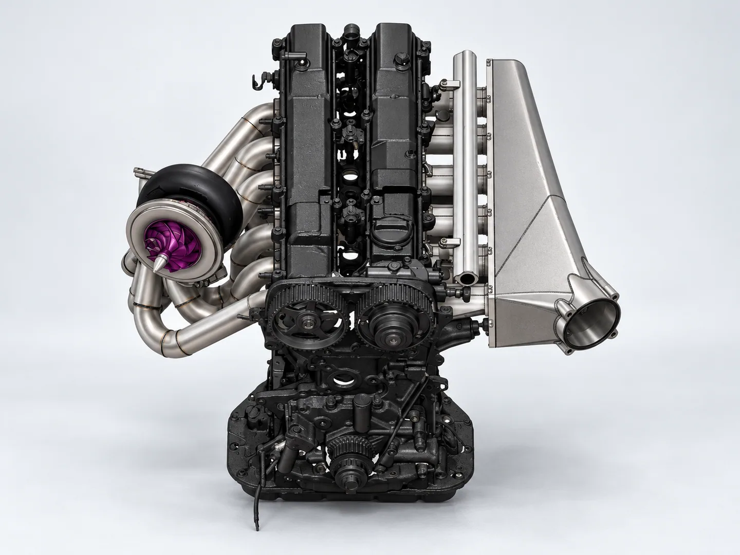
Identify the supplied component within the system
The assembly drawing establishes the boundary of the quoted component. Engine or system datums locate its mounting faces and connections, while neighboring hardware defines installation clearance and tool access.
Identify the individual machined parts, purchased or customer-supplied items, joining and fasteners in the full assembly model. Agree acceptance after assembly.
| Feature | Drawing requirements | Acceptance checks |
|---|---|---|
| Runner geometry | Define internal passages and runner transitions in the full STEP or IGES model. Include sections where access is restricted, with port spacing and flange positions relative to the engine and piping. | Controlled passage and transition geometry. |
| Flange interfaces | Show the port shape, sealing face and bolt pattern at every mating connection. Supply the mating-port drawing and define how the flange interfaces will be checked. | Port, seal and bolt-pattern checks. |
| Installation envelope | Include adjacent components and available clearance, with prototype-fitment checks. Agree pressure, leakage, actuation, flow and cooling tests separately, including procedure, limits and the responsible party. | Separate fitment, pressure or flow criteria. |
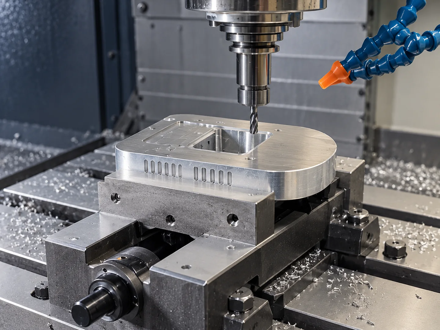
From installation context to machinable interfaces
We use the component model to review each flange, mounting hole and internal feature. Neighboring hardware shows the installation space and cutter access available before we set the machining route.
The quotation identifies the machined pieces, bought-in items, joining and assembly work. Define any power, flow or other performance target with a separate validation plan and assigned responsibility.
Each component drawing and model is assessed for a suitable 5-axis route. The prototype evaluation purpose helps set access and setup requirements.
For intake development, identify the turbo flange, wastegate and piping interfaces included in the prototype. Keep fitment checks and performance testing as separate acceptance requirements.
Related machining and part forms
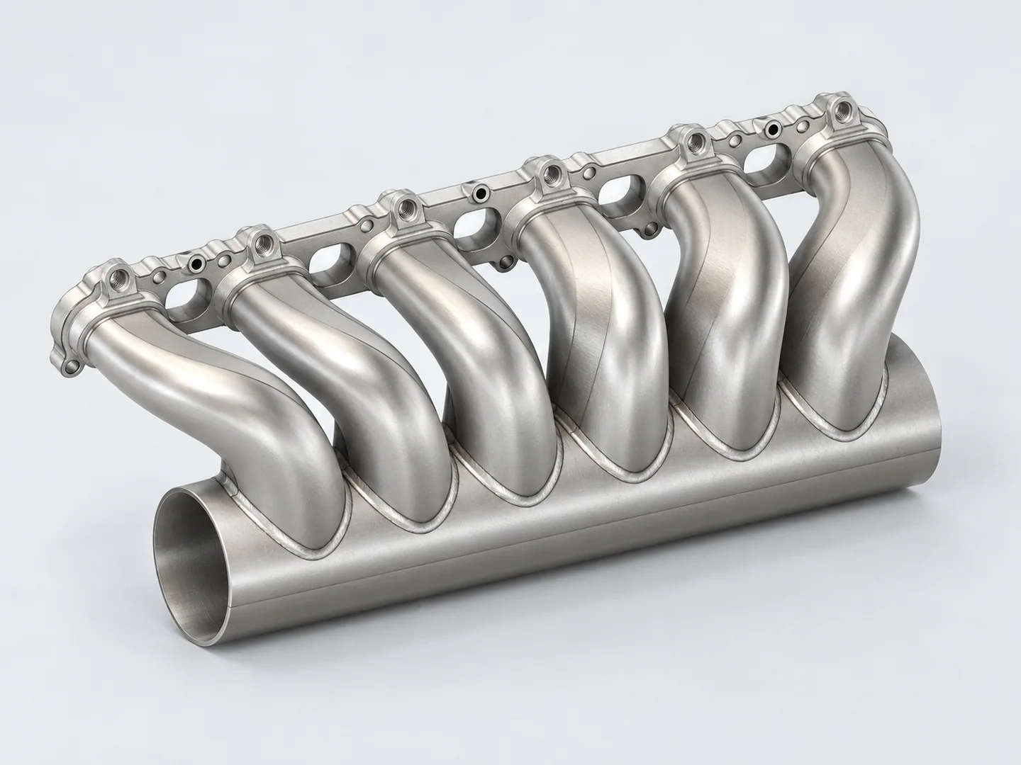
Injector & fuel-rail intake manifolds
For runner geometry and injector or fuel-rail interfaces, see intake-manifold components. Supply the approved revision for each part included in your assembly.
Request a quote for your part
- Assembly & interfacesFull STEP or IGES model, controlled drawing revision and mating-port drawing; identify the machined items, supplied components and prototype-evaluation objective.
- Tests & orderMaterial grade and condition, finish, quantity and destination. Agree pressure, leak or flow tests separately, with procedures, limits and a responsible party.
Tell us how the part will be accepted, including measurement methods, its condition at inspection, sampling and report format.