
Injector & fuel-rail intake manifolds
Curved runners need to meet the mounting flanges, injector seats and fuel-rail interfaces in the approved assembly model. Installation space and access to the internal surfaces determine how these features can be machined.
Use one controlled assembly model for runner, flange, injector and fuel-rail interfaces. Identify each supplied component and its drawing revision.
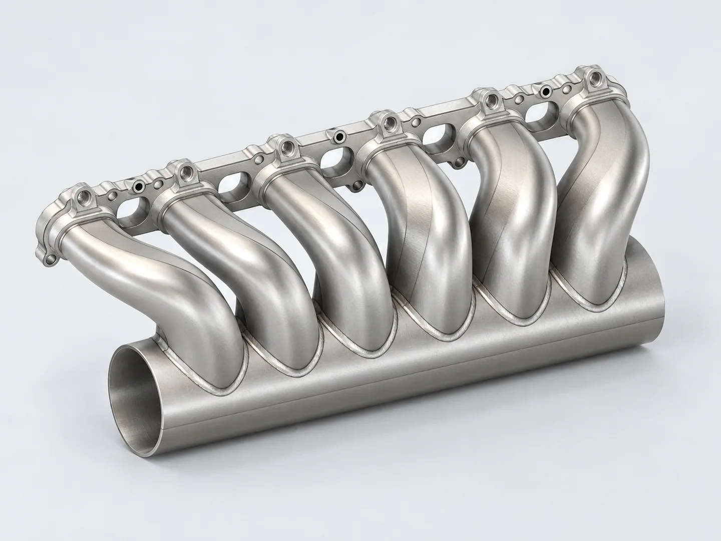
Runners and injector interfaces in one model
Assembly datums locate runner ends and flange bolt patterns. Where injectors or a fuel rail are included, their seats, axes and installation clearances need dimensions in the same controlled model.
Identify the machined parts, purchased or customer-supplied items, joining and fasteners in the assembly drawing. Agree acceptance after assembly.
| Feature | Drawing requirements | Acceptance checks |
|---|---|---|
| Runners & ports | Define curved passages and port transitions in the model, including agreed profiles and the required surface condition. | Agreed runner and port profiles. |
| Injector & rail interfaces | Locate injector bores, their axes and fuel-rail mounts from the assembly datums and intake ports. Supply injector/rail interface drawings with rail-mount positions, and agree injector-alignment and positional checks. | Injector-axis and rail-mount position. |
| Clearance & installation | Show adjacent components and engine-bay or hood clearance. Define prototype-fitment and sealing requirements; agree functional tests separately below. | Fitment and separately defined functional criteria. |
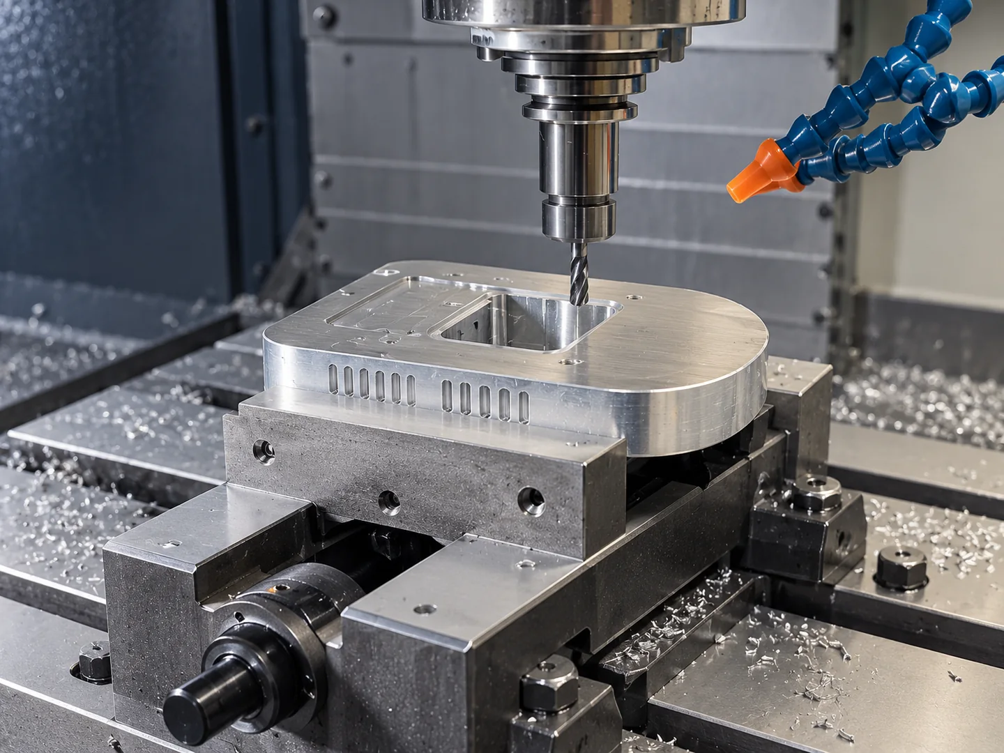
Access to runners and attachment features
We check whether the cutter can reach the curved runners and internal surfaces. Sections and part boundaries help us assess where separate pieces or joining may be needed.
Submit one approved model revision for each supplied part. Define flow, sealing and fuel-system tests separately, including the assembly condition, acceptance criteria and validation responsibility.
The complete STEP or IGES model is the basis for assessing a 5-axis route, including cutter access and engine-bay or hood clearance.
These are design references for custom intake manifolds and automotive prototype assemblies. Your drawing defines the actual application requirements.
Related machining and part forms
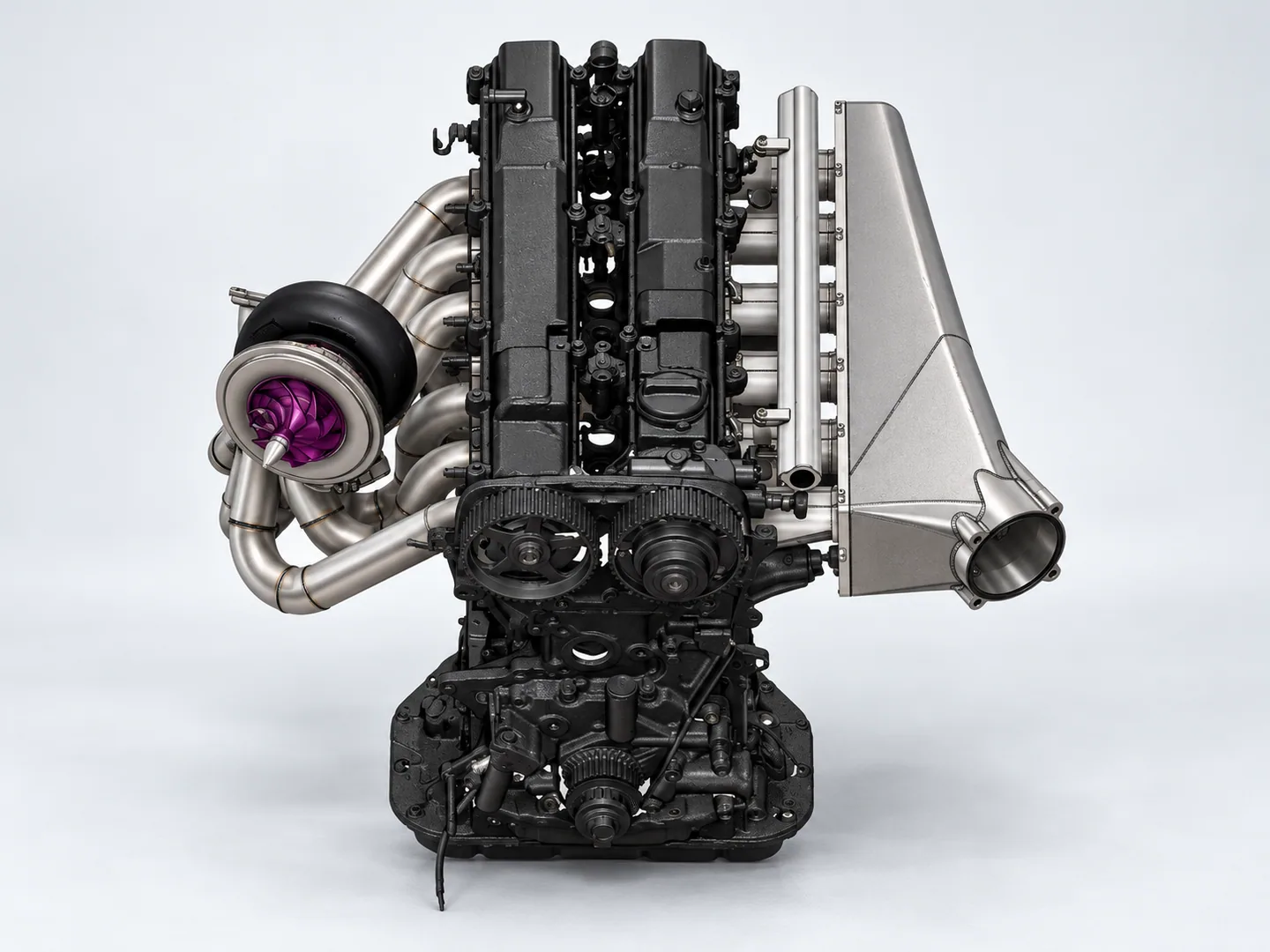
Machined intake-system components
See intake-system components for installation boundaries and neighboring hardware. Manifold components require controlled runner and injector geometry.
Request a quote for your part
- Model & interfacesCurrent controlled model and drawing revision, injector and rail interface drawings, mounting-to-port relationships and installation clearances.
- Evaluation & orderPrototype-evaluation objective, material and finish, quantity and delivery destination; identify any separately required tests.
Tell us how the part will be accepted, including measurement methods, its condition at inspection, sampling and report format.