
CNC machined throttle-body housings
The main bore, shaft supports and actuator attachment need a common alignment in a throttle-body housing. The CAD model and drawing set that alignment, the moving clearances and the mounting pattern.
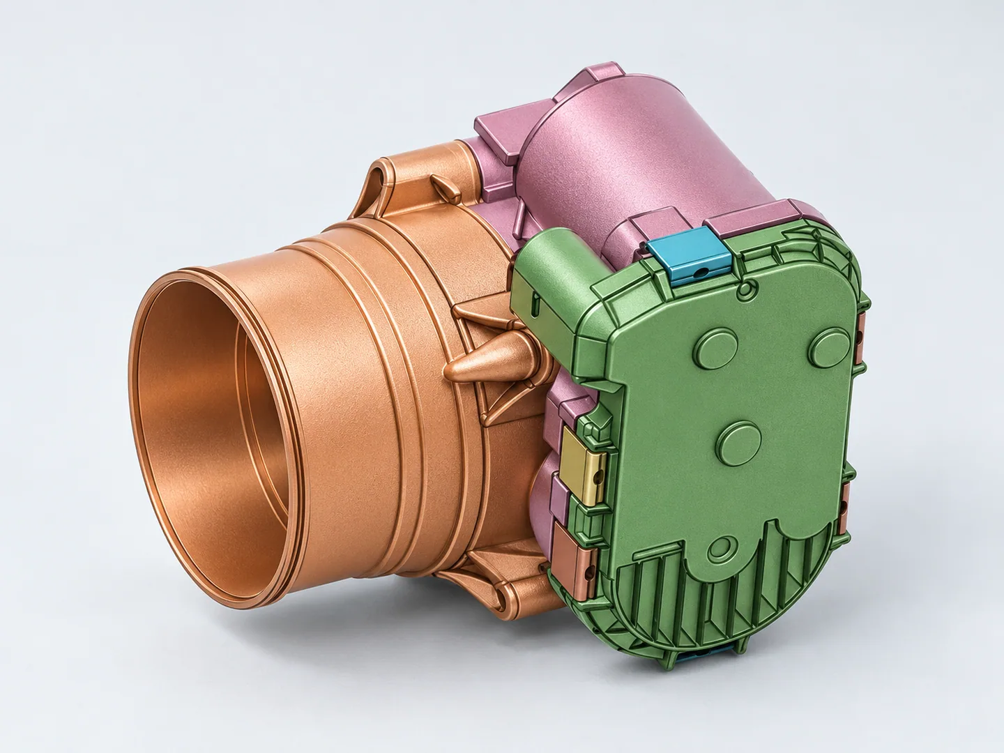
Bore, shaft and actuator interfaces
Sections through the main bore and shaft supports, together with the mating flange and actuator attachment, define the housing. Moving clearances come from the assembly design.
Identify the housing, shaft, throttle plate, motor, gear and sealing features, actuator, electronics, fasteners and any joining included in the quotation. Distinguish machined, purchased and customer-supplied items, and confirm whether the order covers individual components or an assembled unit.
| Feature | Drawing requirements | Acceptance checks |
|---|---|---|
| Shaft, bore and throttle-plate fit | Define the main bore relative to the shaft and throttle plate; bore diameter alone is insufficient. Supply mating components or approved interface drawings with bore size, shaft datum, axis relationships and required clearance or fit. Choose the fit designation for your design. | Bore size, axis relationships and mating fit. |
| Assembly and functional tests | Agree the assembly condition, procedures and acceptance limits for actuation, control behavior, calibration and leakage testing. Confirm test availability and who is responsible; these tests are separate from dimensional inspection. | Component scope and separate actuation or leakage limits. |
| Motor envelope & alignment | Include the motor envelope, bearing and actuator fits, and shaft-bore positions relative to the airflow bore. Specify alignment checks and any electronic-control tests separately. | Agree shaft-alignment and mating-feature checks. Define electronic-control tests separately from housing machining. |
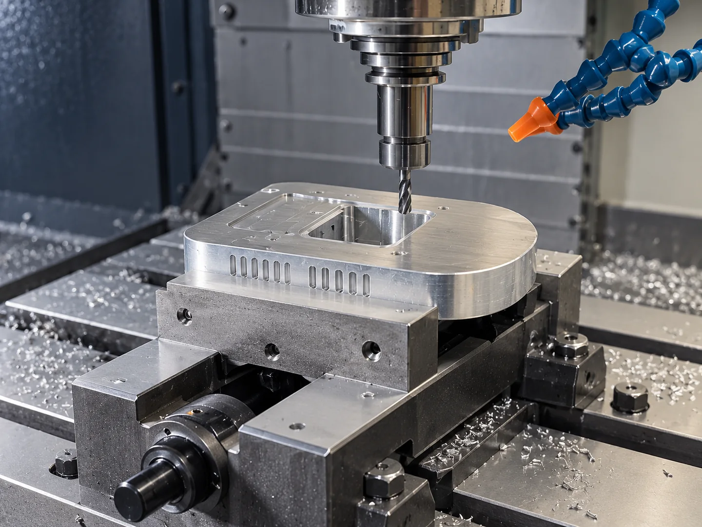
Aligning the bore with the shaft supports
We plan access to the main bore and shaft supports together, using common datums to control their relative position during machining and inspection.
The CAD model and housing drawing are the basis for assessing 5-axis machining.
Related machining and part forms
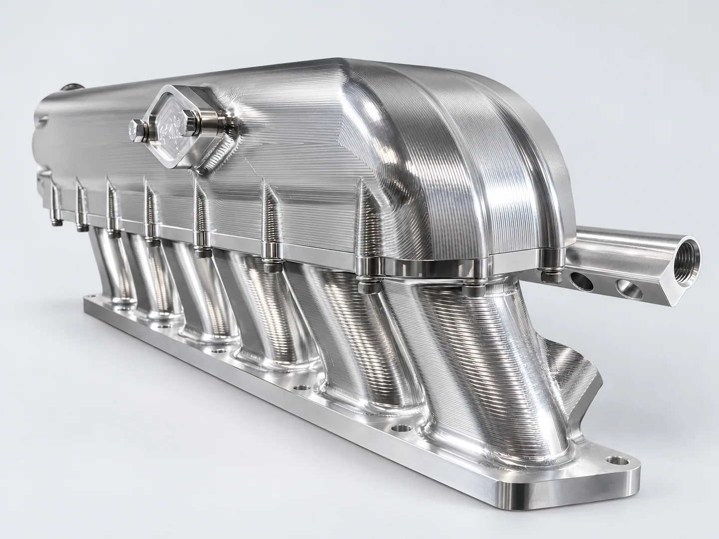
Billet aluminum intake plenums
Intake plenums focus on a chamber and connection ports. A throttle-body housing requires alignment between the bore, shaft and actuator interfaces.
Request a quote for your part
- Interfaces & evaluationControlled model and drawing revision, mating shaft and plate requirements, motor envelope, bearing and actuator fits, prototype-fitment checks and the party evaluating the assembled prototype.
- Material & orderExact grade and condition, finish, quantity and delivery destination.
Tell us how the part will be accepted, including measurement methods, its condition at inspection, sampling and report format.