
Multi-sided machined components
Each perimeter connection needs a position and tool approach relative to the central bore and mounting face. Section views show how any internal passages connect inside the circular body.
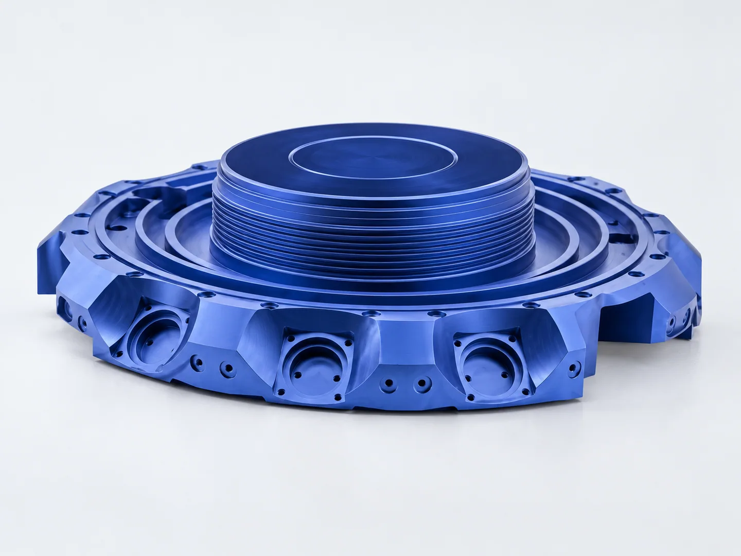
Connection axes around a circular body
The drawing locates each perimeter connection by angle, height and offset from the central reference. Sections define any communicating passages and the surfaces that must seal.
Include the complete model and datum scheme so we can review the small interfaces that are unclear in the photograph.
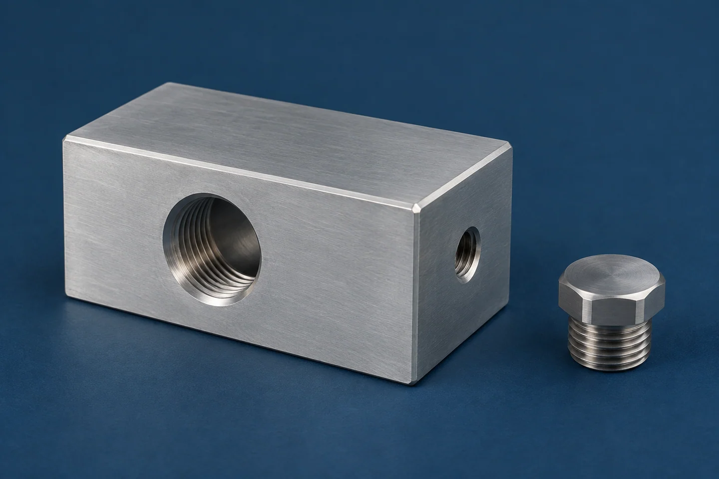
| Feature | Drawing requirements | Acceptance checks |
|---|---|---|
| Multi-face datums | Locate the working faces and hole patterns from common drawing datums. Mark feature positions and dimensions that cross between faces. | Feature positions from shared datums. |
| Ports & bores | Specify bore depths, intersections and connection details, with sections where needed. Include angled-port standards and mating hardware; agree separate sealing-test criteria. | Port standard and separate sealing criteria. |
| Setup access | Identify assembly clearances, clamping restrictions and finished surfaces to protect during repeated setups. Specify mounting-pattern positions, face orientations and their acceptance limits. | Mounting-pattern position and orientation. |
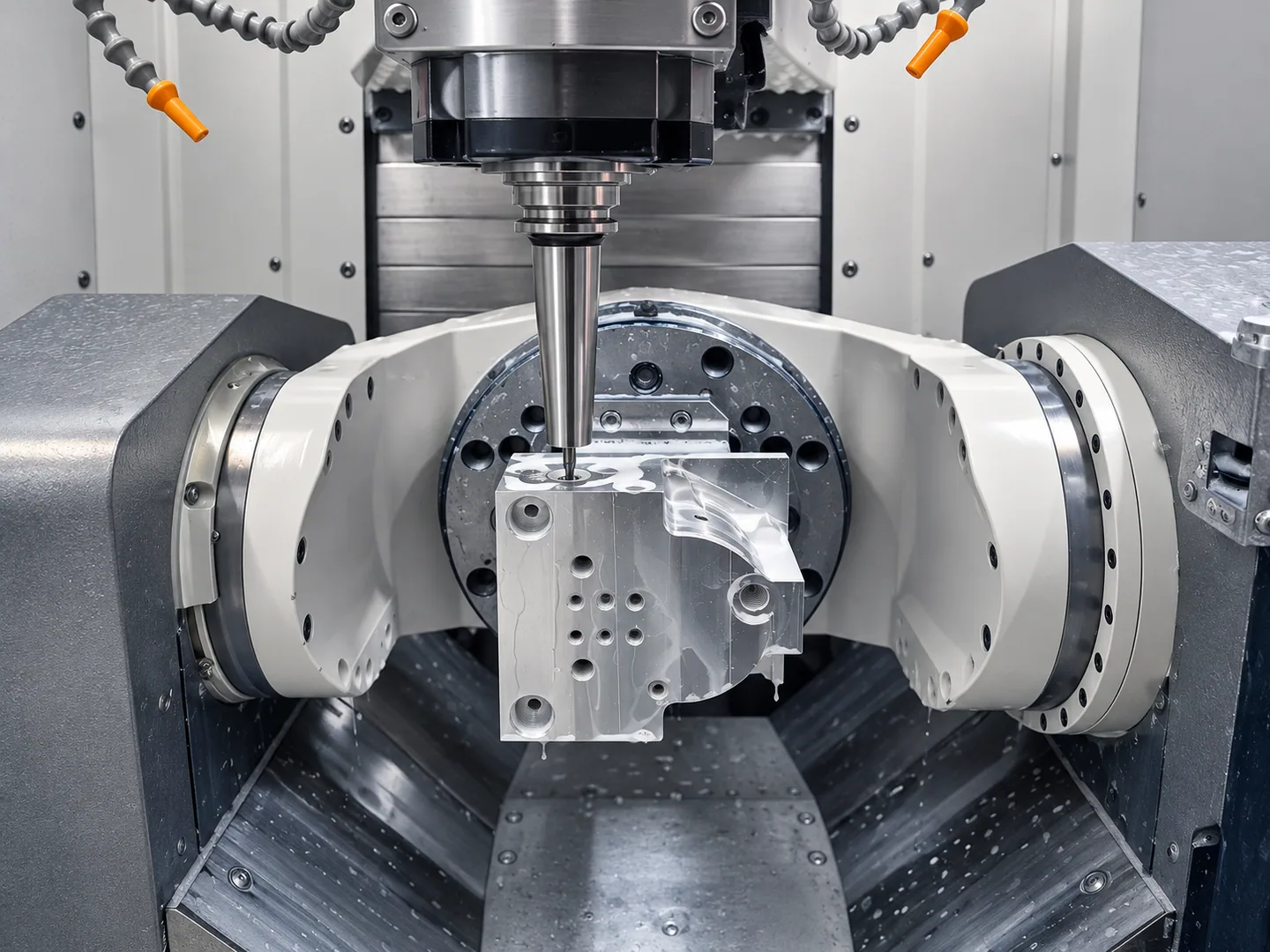
Indexing the perimeter features
We machine the perimeter connections from different directions, locating each setup from the central and axial datums. The model shows which holding positions give the cutter access to every connection.
Where bores intersect, include sections through the junctions and specify burr-removal and inspection requirements. The drawing must define the complete internal fluid path.
Multi-axis and 5-axis machining with component-specific fixturing.
For instrumentation, energy equipment and multi-port assemblies, define each port connection and its relationship to the main bore. Include fluid compatibility and any required pressure or leak testing.
Related machining and part forms
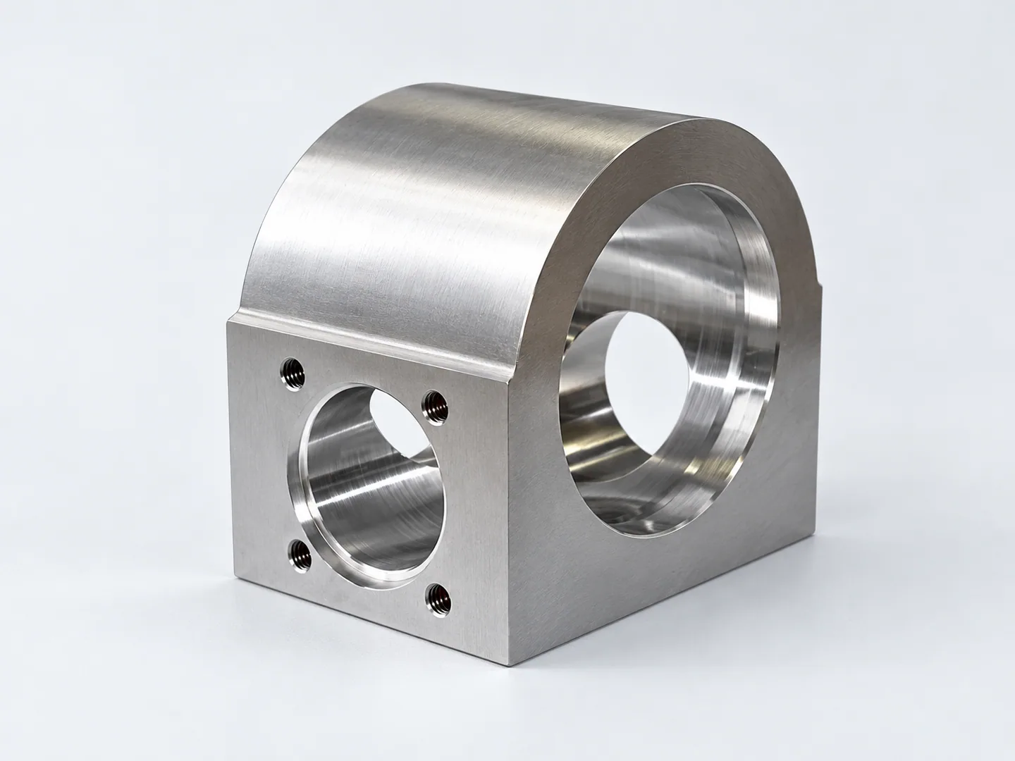
Milled instrument blocks & brackets
Blocks and brackets use datums on prismatic mounting faces. Here, connection angles and offsets are located around a common circular body.
Request a quote for your part
- Geometry & assemblyComplete model and controlled drawing revision, port standards, mating hardware and assembly access constraints.
- Acceptance & orderFeature limits, material grade and condition, finish, quantity and delivery destination. Agree separate sealing tests where required.
Tell us how the part will be accepted, including measurement methods, its condition at inspection, sampling and report format.