
Turbine & fluid-system components
A recessed hub restricts access to the inner blade roots and mounting bore. The complete model needs to show the blade passages and hub recess, with the mounting face and bore located from the specified datums.
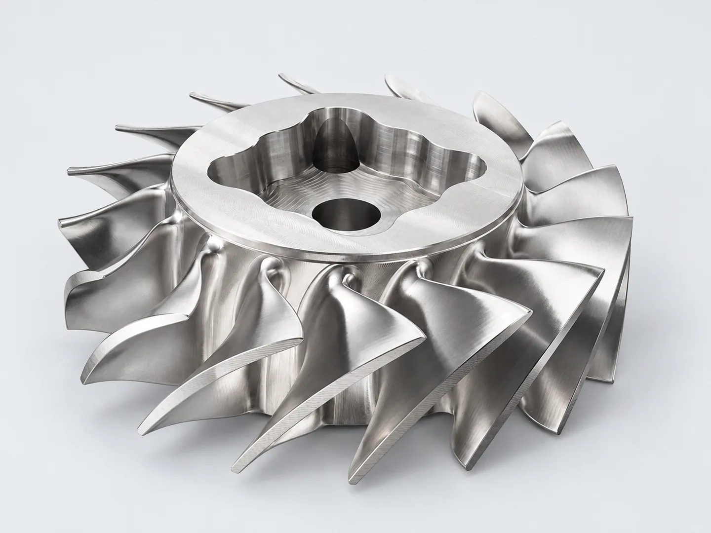
The recessed hub and surrounding blade passages
Sections through the hub recess and blade roots show where the tool must reach. The drawing defines mounting surfaces, profile tolerances and edges; operating-duty requirements are specified separately.
| Feature | Drawing requirements | Acceptance checks |
|---|---|---|
| Curved flow surfaces | Supply the controlling model for contours and transitions. Mark surfaces requiring profile inspection and model comparison. Specify any CMM comparison to the 3D model, reports and traceability. | Profile comparison to the model. |
| Hub & mounting geometry | Common datums and a datum axis connect bores, mounting faces and curved features. Locate the hub, sealing interfaces and ports from those references. | Hub and interface position. |
| Operating requirements | Identify the intended fluid and assembly context. Agree balance, rotating-assembly, pressure, flow, leakage and other performance tests separately from dimensional inspection. Define assembly conditions, procedures and acceptance limits, and confirm availability and responsibility before ordering. No efficiency or reliability rating is established for this example. | Separate balance, pressure or performance criteria. |
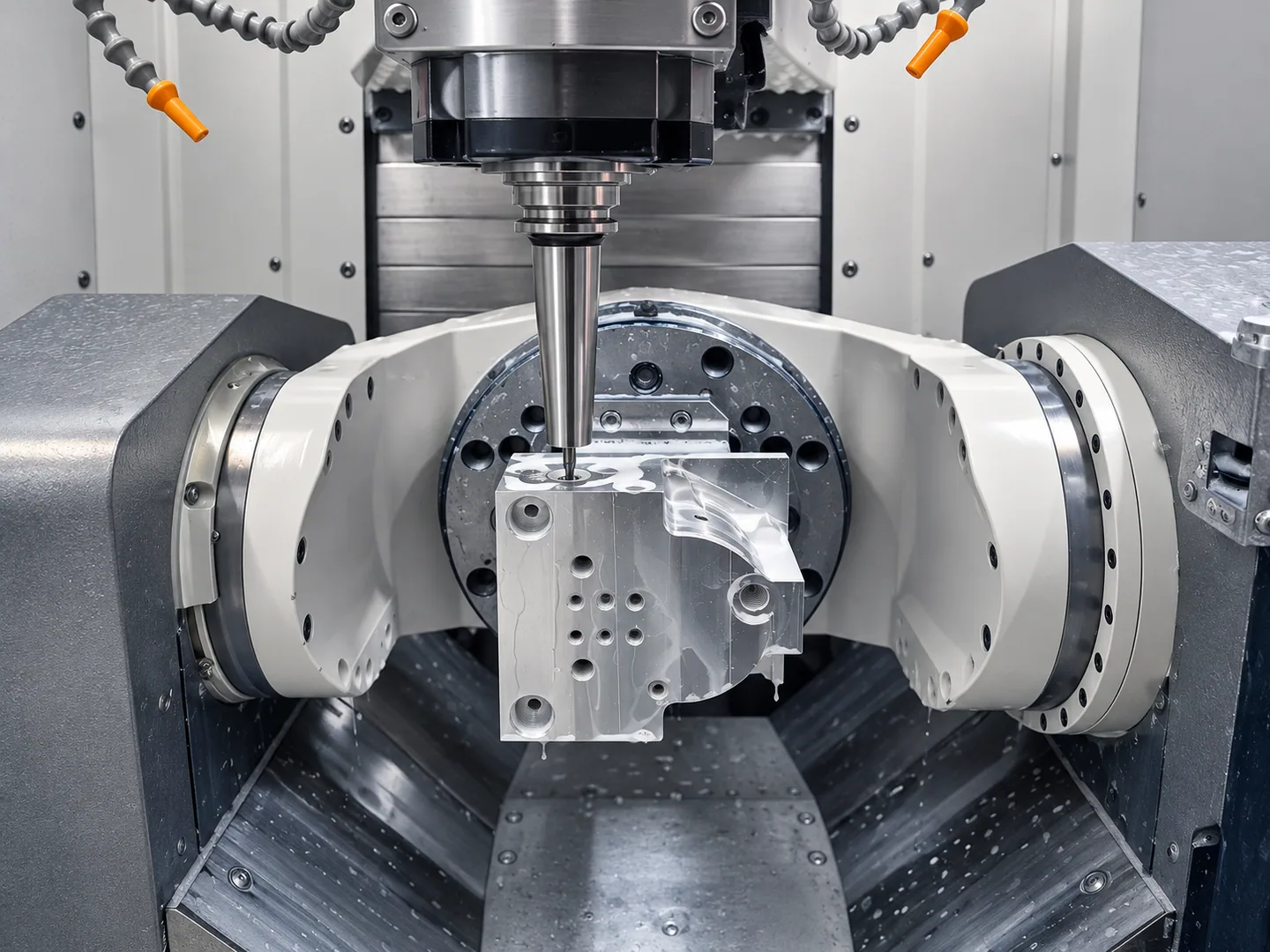
Reaching into the hub recess
The recessed hub leaves limited access to the inner blade roots and central mounting features. We check cutter-holder clearance between the blades before choosing the tool orientations.
Specify profile and dimensional acceptance for the machined surfaces. Balance, flow and rotating-duty validation need separate test criteria and responsibility.
5-axis contour machining.
For turbine components, fluid housings and other curved parts, define the working profile and its relationship to the hub or mounting interface. Include the operating conditions and any functional-test requirements.
Related machining and part forms
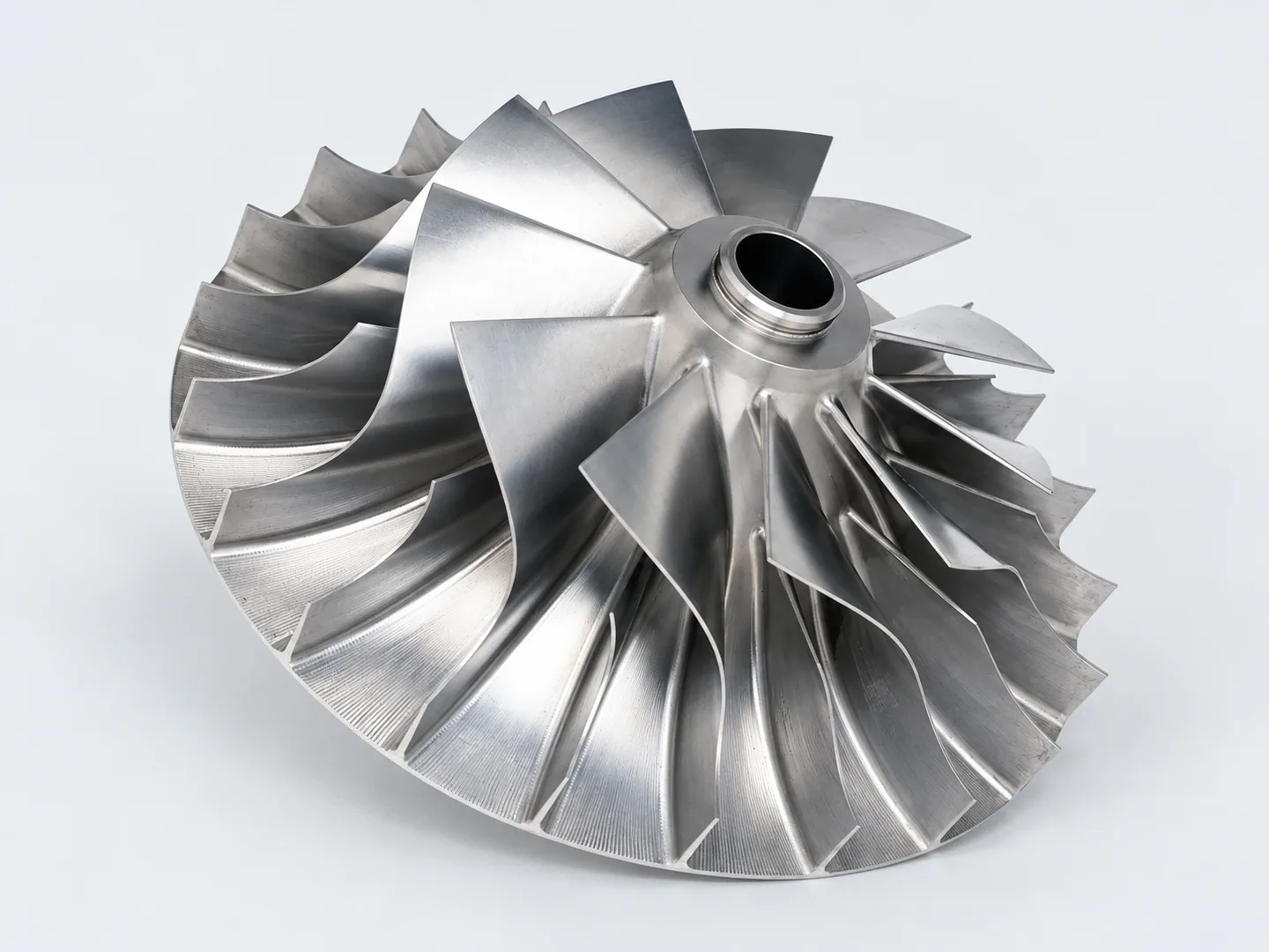
Custom CNC Impeller Machining
The tall-hub impeller has a different clearance problem between its blades. This shorter form requires access into a recessed center.
Request a quote for your part
- Model & validationControlled model revision and feature requirements. State who will validate each functional requirement and the separately agreed test criteria.
- Material & orderExact grade and condition, treatment of flow and mating surfaces, quantity and delivery destination.
Tell us how the part will be accepted, including measurement methods, its condition at inspection, sampling and report format.