
Custom CNC Impeller Machining
The tall hub restricts cutter and holder clearance between the impeller blades. We review the blade surfaces and root transitions together with the hub bore, so the machining plan covers both root access and the mounting features.
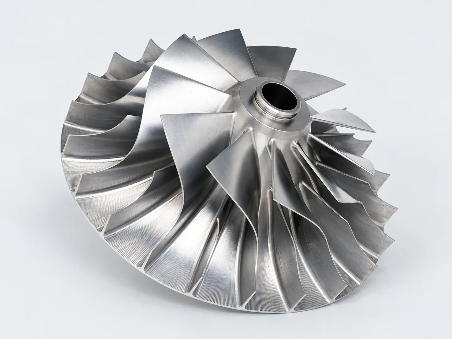
Blade passages, roots and the tall hub
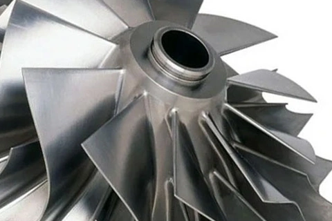
The complete blade model and sections through the roots are needed for machining review. Blade thickness, profile tolerances, hub-bore fit and the axial locating face belong on the drawing, with edge requirements specified separately.
Specify feature-specific tolerances on the controlling model and drawing. No numerical tolerance is specified for this example.
| Feature | Drawing requirements | Acceptance checks |
|---|---|---|
| Blade profiles | The controlling 3D model supplies the curved blade surfaces. Identify the profiles to inspect, their agreed limits, measurement methods and required records. | Agreed profiles against the controlled model. |
| Blade roots & tool access | Identify workholding surfaces and cutter access at the blade-to-hub transitions. Mark thin sections and root geometry, including any radius or thickness changes that need approval. | Root geometry, thin sections and permitted changes. |
| Hub bore & datum axis | The hub bore, mating fit and datum axis need a common definition, with their relationships to the blade geometry shown on the drawing. | Hub fit and relationship to the blade geometry. |
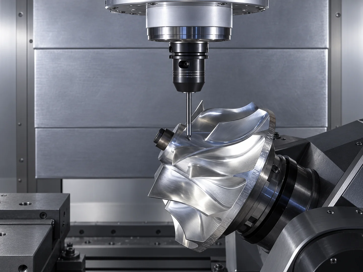
Reaching the roots between curved blades
We check how blade curvature and hub height affect cutter approach and holder clearance. Each blade root needs review for surfaces that require another tool orientation or finishing operation.
Define profile inspection for the blades and dimensional checks for the hub interface. Balance, operating speed and fluid-performance tests require their own criteria and agreed validation scope.
Curved surfaces and deep cavities can make continuous 5-axis machining worth considering to reduce repositioning. The model, cutter access and fixture clearance determine the route and setups.
For aerospace, scientific equipment, robotics and industrial-fan projects, define blade profiles and hub interfaces in the controlled model. State any balance, speed, efficiency or application-specific qualification requirements separately.
Related machining and part forms
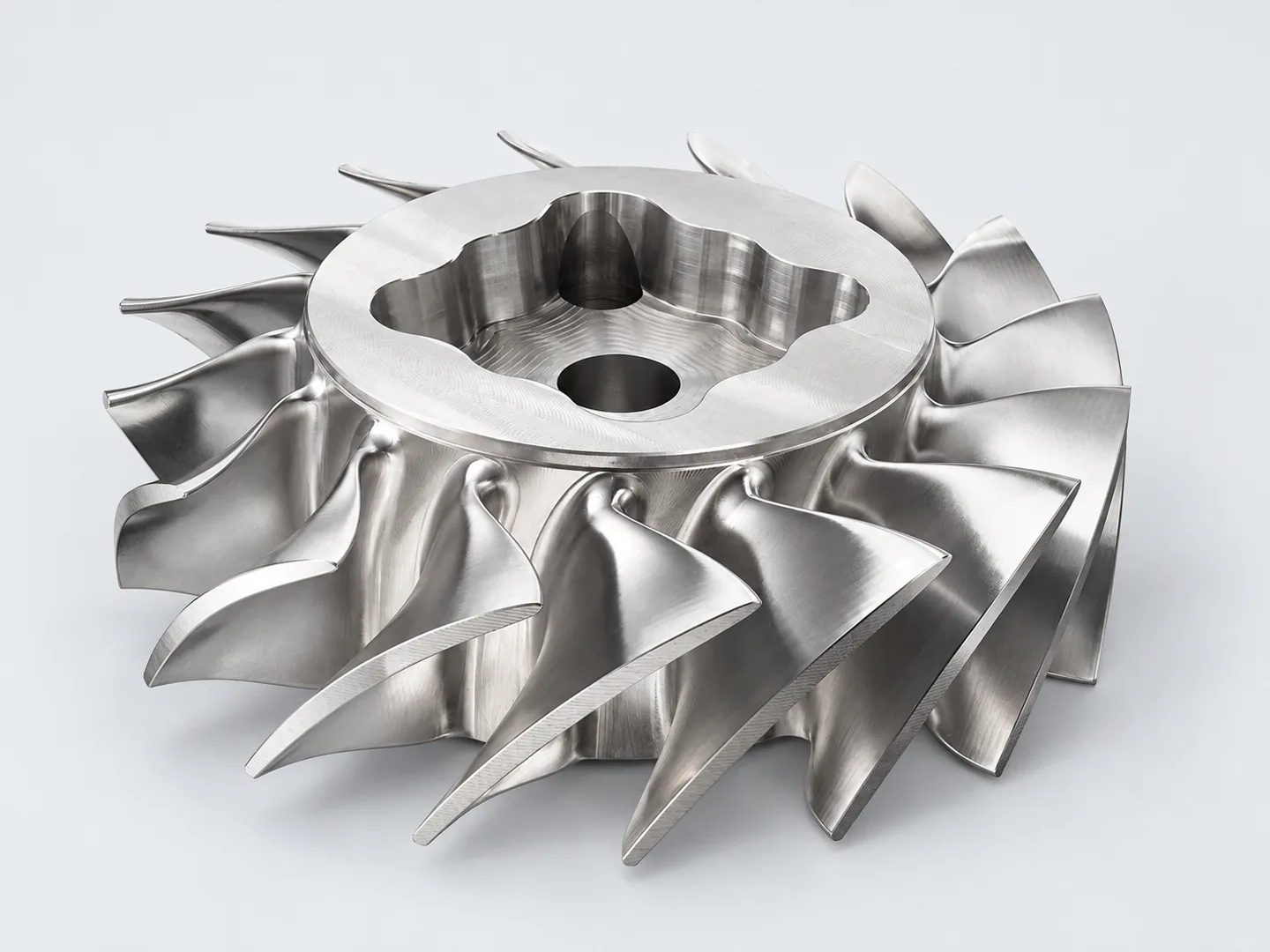
Turbine & fluid-system components
Compare the curved-blade component with a recessed hub for a different access problem at the center of the part.
Request a quote for your part
- Files & profilesControlling model and revision, critical blade profiles, datum axis, feature-specific tolerances and required profile records.
- Material & orderExact grade and material condition, quantity and delivery destination.
- Operating scopeIntended operating context and any separately agreed tests.
Tell us how the part will be accepted, including measurement methods, its condition at inspection, sampling and report format.