
Open CNC machined aluminum enclosures
Side openings and projecting mounting ears limit where an open aluminum enclosure can be clamped. Wall support and cutter access must leave the ear holes aligned with the internal mounting faces.
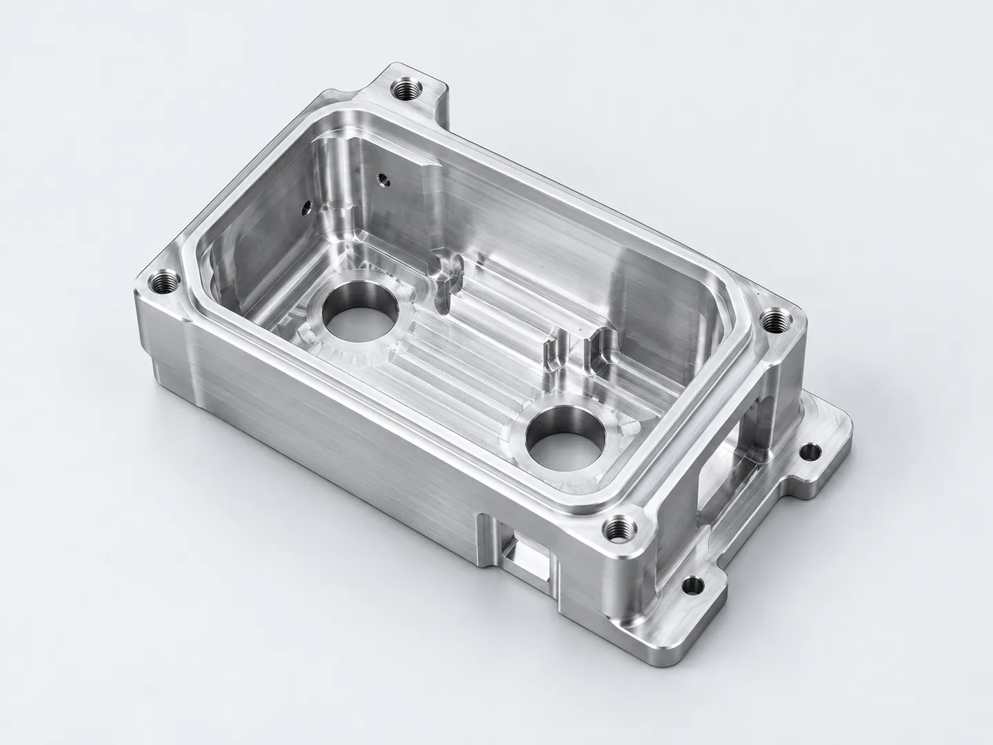
Side openings and projecting mounting ears
Side cutouts share assembly datums with the mounting-ear holes and internal faces. Wall sections around the openings and material supporting each ear let us assess clamping and tool access.
| Feature | Drawing requirements | Acceptance checks |
|---|---|---|
| Cavities & mounting interfaces | Locate pocket depths, side openings and mounting features from specified assembly datums. Include stock form and alloy condition. State flatness and hole-position limits for the mating interfaces. | Positions from specified datums. |
| Walls & any angled features | Specify wall sections, depths and support areas. Where compound-angle features are required, locate their faces and relationships from mating datums and define checks in the model. | Wall, depth and any defined angled-feature checks. |
| Repeat setups & final condition | Identify feature limits to retain through repeated setups, finish specification and post-treatment acceptance dimensions. Agree required batch records, sampling and reporting. | Post-finish dimensions and batch records. |
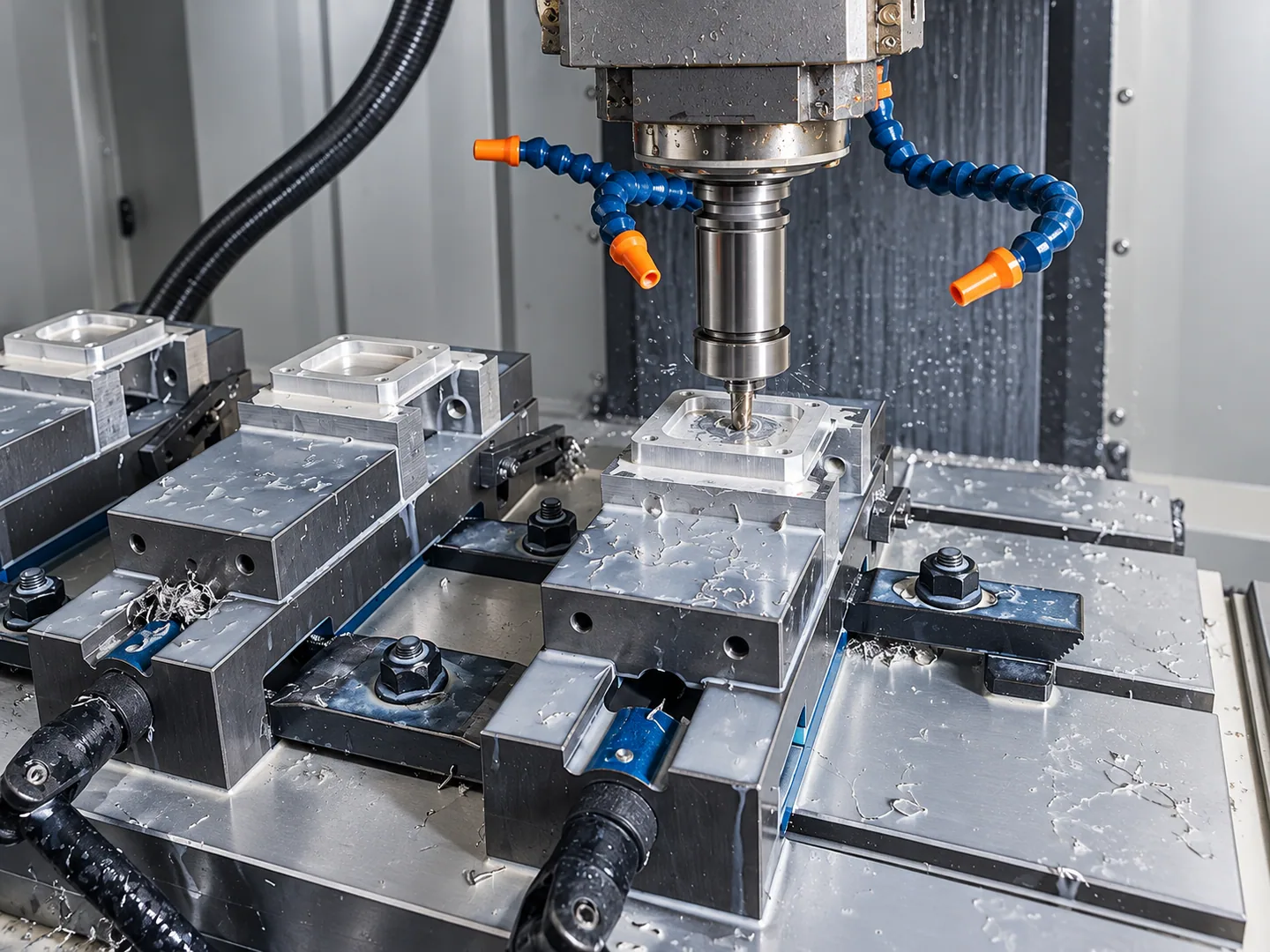
Reaching the side walls while supporting the enclosure
We plan the floor, walls, side openings and mounting holes as one setup sequence. Projecting ears leave fewer clamping positions, and the side features need cutter access outside the cavity.
Set the final wall and mounting requirements after machining and finishing. For repeat quantities, agree dimensional checks, sampling and release records for the later parts.
The model determines which milling, turning, 5-axis or cast-blank finishing operations are needed. Thin walls also need stress-relief planning and consistent fixtures across setups.
These forms are references for complex enclosures and small-batch structural parts. Your drawing defines the application requirements.
Related machining and part forms
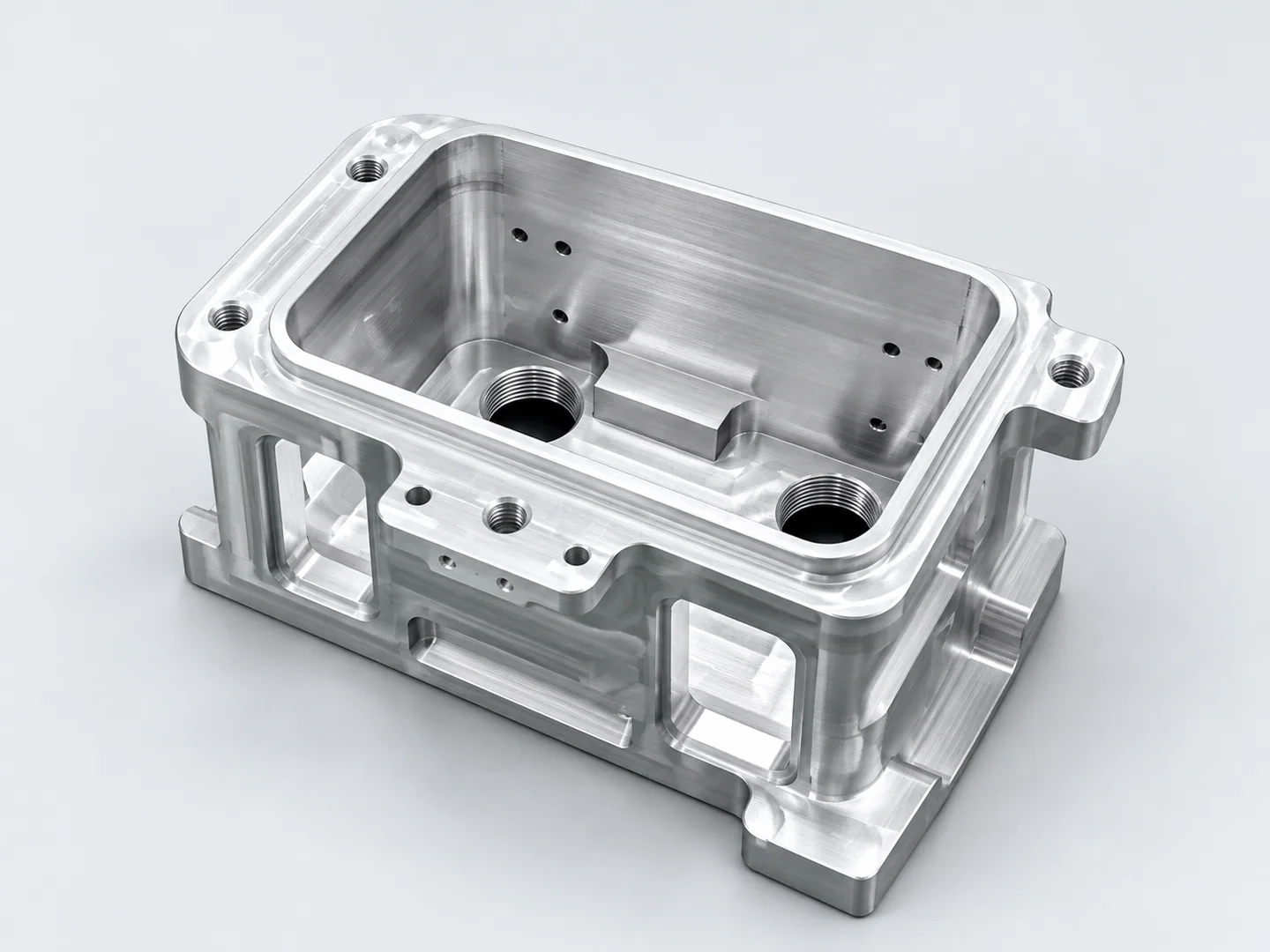
Pocketed aluminum housings
Pocketed housings emphasize the cavity and closure interface. Open enclosures also require side-wall access and support around projecting mounting ears.
Request a quote for your part
Order and release requirements
Each part number needs an approved revision, material condition, finish, release quantity and requested date, with shared interfaces and change authority identified. The order sets first-article checks, later sampling, traceability and nonconforming-part handling. Forecast demand stays separate from firm release quantities.
- Geometry & stockControlled model and revision, stock form, alloy and condition, mounting datums and critical cavity or wall requirements.
- Final condition & orderFinish specification and protected fits, quantities per revision, required reports and delivery destination.
Tell us how the part will be accepted, including measurement methods, its condition at inspection, sampling and report format.