
Specifying a Billet Intake Manifold for Machining
A billet intake manifold component is machined from solid stock. Its internal passages and mating faces must match the cylinder-head, throttle and seal interfaces specified for the assembly. A machining quote needs those definitions and a clear supplied-item list, including any hardware, joining work and functional checks.
On this page
Define the components that the manifold must meet
A manifold is part of a larger assembly. Its runner flanges, throttle connection, injector locations and mounting features must match the approved mating components. Give those interfaces controlled drawing references instead of expecting the machining supplier to infer an engine configuration from the outside shape.
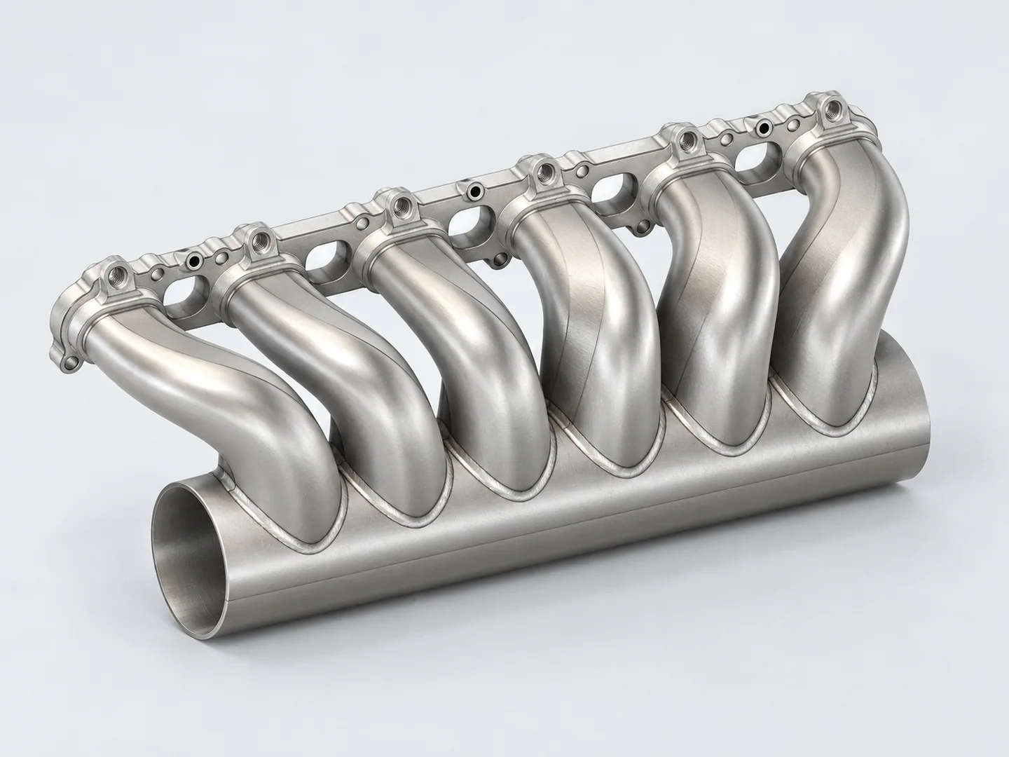
The intake-manifold reference joins several runners to a shared passage and flange. Each runner opening needs to meet its intended port, while the mounting pattern and seal faces keep that relationship in the assembled position. Those interfaces should be visible in the controlled model and assembly drawing.
List the components that establish fitment. Depending on the supplied design, these may include the cylinder-head interface, throttle body, selected seals, injector hardware or mounting brackets. State which drawings or models control each connection and identify any component that the customer will supply for review.
Holley’s intake-manifold technical support addresses head, port and gasket compatibility for its products. A custom manifold needs the corresponding details for its own assembly. Product-specific installation instructions cannot establish that fitment.
A vehicle or engine name is not the mating definition
For the multi-runner reference shown here, the useful fitment inputs are the approved port locations, flange faces, mounting pattern and selected seals. A vehicle description can help identify the project, but it does not establish those dimensions or the revision of each mating component. Supply the controlling head, throttle and other interface drawings available for the actual design.
Resolve any missing interface before treating the model as released. If the customer supplies a mating component for a trial, record its identity and the purpose of that check. A successful fitment trial on that configuration does not establish compatibility with an unreviewed engine variant.
Make the internal surfaces part of the controlled model
External views cannot fully define the runner transitions or the inside of a chamber. Supply section views and a model containing the complete internal surfaces. Identify any region where a profile, transition or surface requirement is essential to the design and which areas may be discussed for machining access.
One-piece and split billet intake-manifold construction
A split design can expose internal surfaces for cutting and inspection before closure. It also adds an assembly joint that must locate and seal correctly. The model review can compare these requirements before the component drawings are released.
| Design question | One-piece construction | Split construction |
|---|---|---|
| Tool access | The complete passage needs a practical cutting approach through the available openings. | Open components can expose regions that become enclosed after assembly. |
| Passage alignment | The geometry is controlled within the single part and its machining references. | Registers or other locating features must control the relationship across the joint. |
| Sealing and retention | Connections to mating hardware still need specified seals and mounting features. | The added split needs its own joint surfaces, seal and retention definition. |
| Inspection stage | Internal access depends on the openings left in the finished component. | Relevant internal checks can be planned before closure, followed by assembled checks. |
For a split runner or plenum, the fasteners and locating features have different jobs. Clearance fasteners can retain the joint while a register, dowel or other defined feature locates it. The drawing should control any step across the passage and the surfaces used to establish alignment.
The seal needs a supported contact region around that joint. Bolt access, surrounding wall thickness and the space left for tools all belong in the same section review. A joint that is convenient to machine can still be awkward to assemble or inspect if the retained hardware blocks access.
Related CAD files need a common revision basis. A chamber model, runner model and reference assembly can disagree even when their part names look consistent. Confirm how the released components fit together and which file controls each surface or interface.
Small internal details can change access for tools, deburring and inspection. Include blind intersections, recessed ports and any cavities that will become closed later. The supplier needs a way to assess the required internal condition before final assembly makes it inaccessible.
Where an internal finish is specified, define the relevant region and measurable requirement. A broad instruction to make all passages smooth gives little basis for comparing scope or accepting a finished surface. Connect the chosen finish to the design requirement without assuming an operating-performance result.
- A · Runner flange, seals and mounting pattern
- B · Controlled internal chamber and passage geometry
- C · Throttle interface and required clearance
Keep the interfaces and their checks identifiable
| Interface | Information to supply | Acceptance to define |
|---|---|---|
| Runner or head flange | Controlled port profile, bolt pattern, reference faces and seal. | Position, mating-face geometry and the specified surface condition. |
| Throttle connection | Mating component, opening, mounting pattern and clearance envelope. | Fit, orientation and seal-interface checks. |
| Injector or auxiliary port | Approved hardware, location, orientation and connection details. | Feature dimensions and any separately required functional test. |
| Split joint | Mating geometry, fasteners and selected sealing arrangement. | Joint alignment, surface condition and assembled acceptance. |
| Internal passage | Complete controlled model and any restricted changes. | Defined profile or surface checks and access before closure. |
Specify material and condition for each machined component. If a part receives treatment after machining, identify its influence on the final fits and contact surfaces. Keep inserts, fasteners and seals identifiable in the component or assembly definition.
Clamping and tool access also need the full outside envelope. A part that can be reached in a model view may still need additional holding orientations. Mark protected faces and discuss any temporary stock or locating features before the manufacturing revision is approved.
Settle component supply and functional testing separately
A quotation for a machined manifold component may exclude the hardware and work needed for a ready-to-install assembly. List the mating pieces, inserts, seals and fasteners included in the order, along with responsibility for joining and assembly. Record the items supplied or arranged separately.
Dimensional inspection verifies the specified geometry. A fitment check needs the agreed mating components or a controlled equivalent. Leakage testing requires its own configuration, conditions and acceptance limit. These activities should be named separately so a report for one is not mistaken for completion of all three.
Flow or operating-performance requirements need a suitable test plan and responsible party. A billet construction, internal appearance or dimensional result cannot establish a particular power or flow improvement. If those outcomes are part of the design program, identify how and by whom they will be evaluated.
A prototype can help resolve interfaces before a repeat release. Record its configuration, drawing revision, completed checks and any accepted exceptions. If a mating throttle, seal or runner design changes later, review the corresponding measurements and functional acceptance before repeating the earlier approval.
Our aluminum machining review focuses on the controlled components and the agreed order scope. Include any required joining or outside testing in the initial discussion so the quotation can identify what is included and what needs a separate arrangement.
A manifold package ready for manufacturing review
Keep the models, component list and interface requirements under revision control. Mark unresolved design decisions alongside the affected surfaces so a complete-looking model is not mistaken for an approved manufacturing definition.
- Released models and drawings for each runner, chamber, flange or other supplied component.
- Mating-component definitions, seal specifications and relevant assembly clearances.
- Material, condition, surface requirements and final dimensions after any treatment.
- Internal profile control, permitted geometry changes and access for inspection before closure.
- Component or assembly supply, included hardware and responsibility for joining or assembly.
- Dimensional records, fitment acceptance and any separate leakage or performance-test plan.
- Prototype approval, order quantity and the revision basis for a repeat batch.
Keep the accepted mating components, seals and agreed check results with the released part drawings in the sample approval record. The next order can then refer to the configuration that was reviewed, with unresolved tests still identified.