
Flanged turned component assemblies
Flanged turned assemblies bring bodies, handles and fasteners together around shared bores and mounting faces. Each machined component needs its own mating-fit definition, followed by a separate assembly and functional-check scope.
List each machined component, fastener and required marking. Agree assembly and functional tests separately.
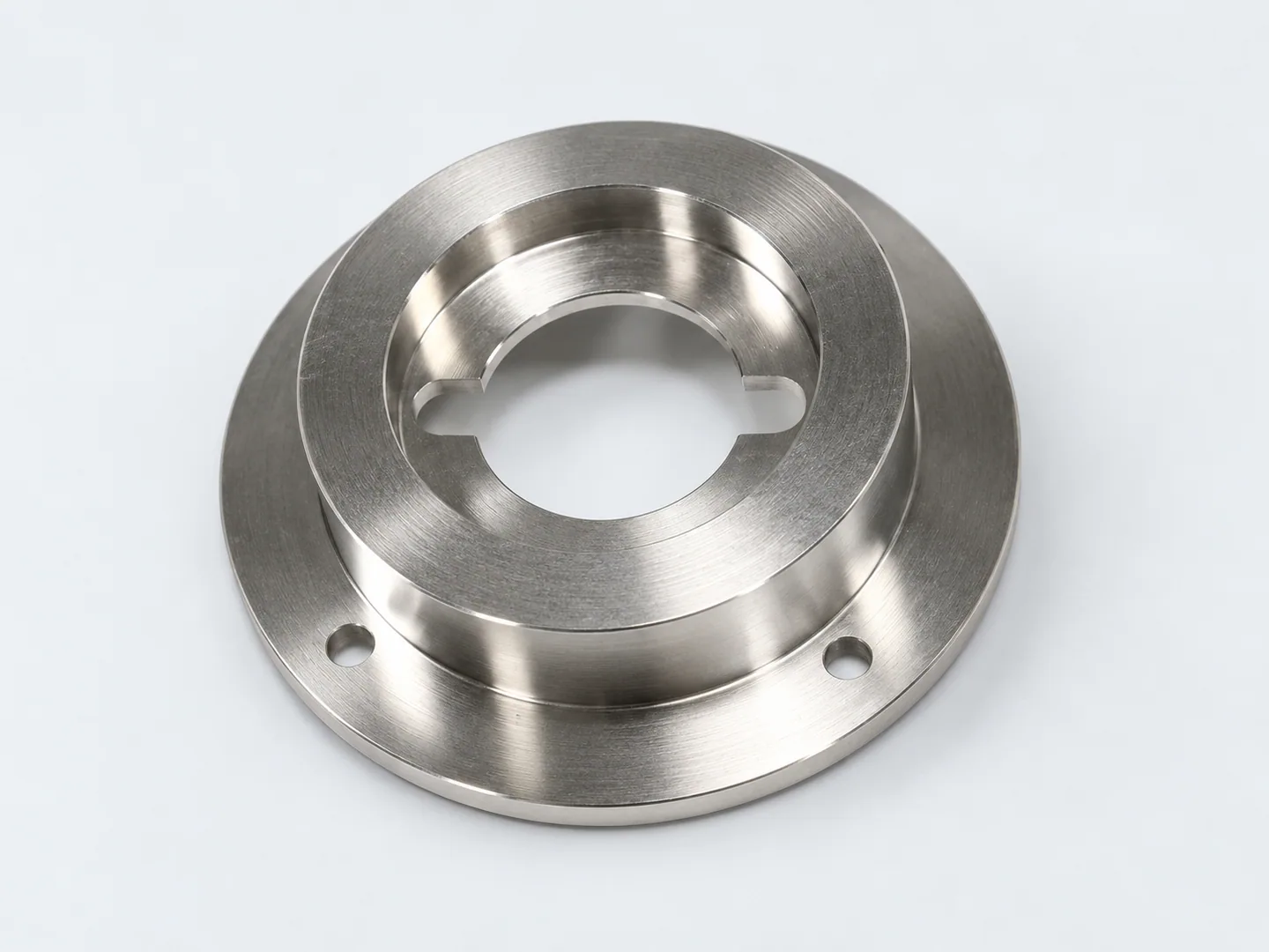
The flanged forms and their component boundaries
The parts list separates turned bodies, flanges, handles and fasteners. The assembly drawing locates bores and mounting holes from the working flange face, with mating fits and any required orientation.
Use controlled component drawings to define the visible parts and any hidden working features.
| Feature | Drawing requirements | Acceptance checks |
|---|---|---|
| Flange faces & bore axes | Define flange faces, bore sizes and fits, face relationships and mounting holes from common datums. For hidden working diameters, threads, sliding or off-axis features, specify fit, thread standard, angular reference and surface condition, with runout and thread gauging where required. | Bore size, flange faces and hole positions. |
| Fasteners & direction marks | Specify screws, countersinks, ON/OFF text and arrow artwork, including marking orientation, appearance and process. | Marking orientation, appearance and screw specification. |
| Component & assembly scope | List machined pieces and purchased hardware, showing hidden interfaces on the drawing. Agree assembly scope and acceptance. Pressure, leakage, actuation, flow, cooling or other functional checks need separate assembly conditions, procedures, limits and a responsible party. | Agreed assembly scope and separate functional criteria. |
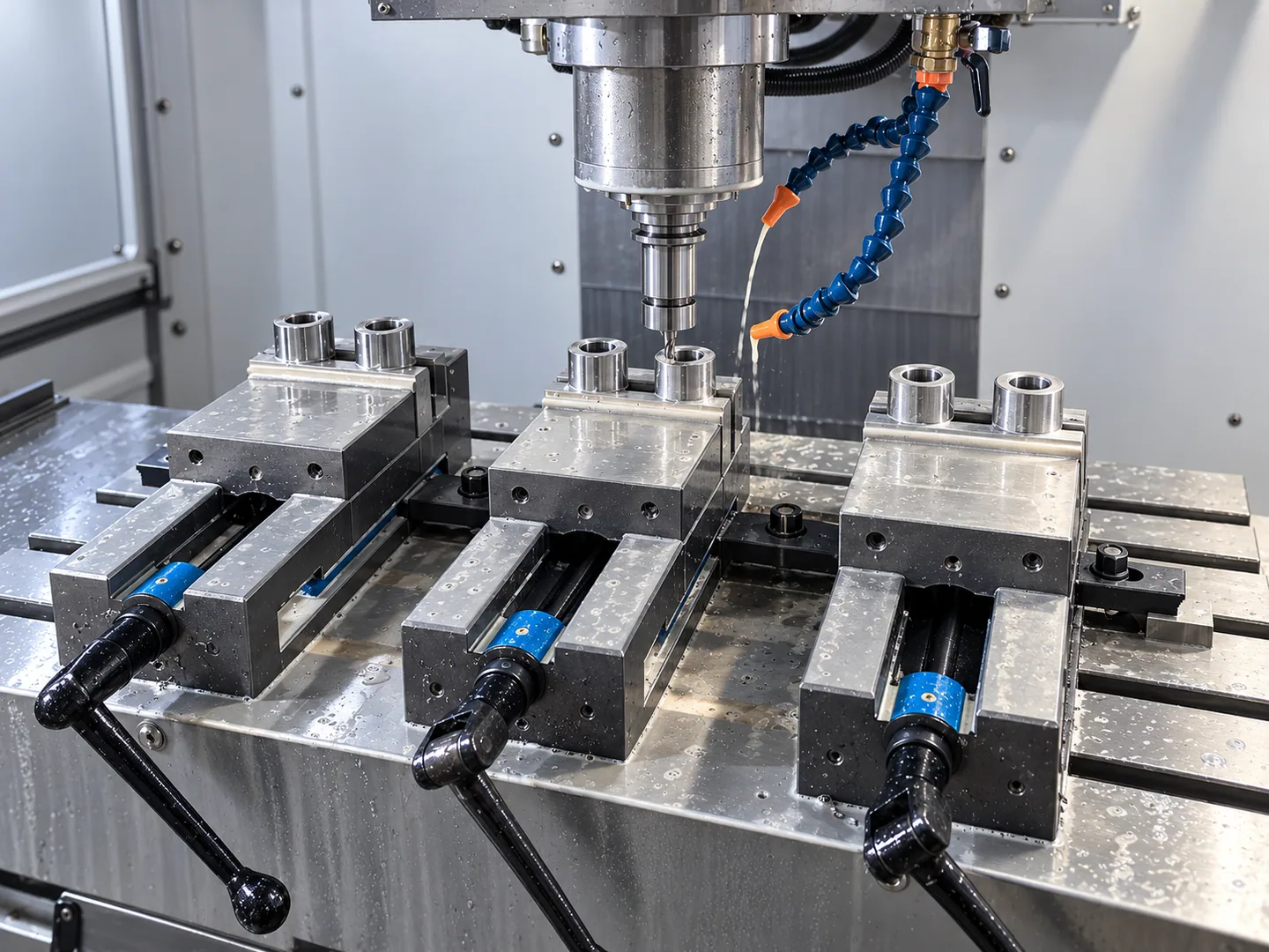
Relating flange faces to the turned bore
We locate the secondary mounting holes from the flange face and central bore. The inspection plan distinguishes dimensions checked on individual components from those checked after assembly.
Where the order includes a mechanism, provide its component drawings and assembly definition. Specify torque, locking and functional-test criteria with the required markings.
The component drawings guide turning and live-tooling operations, including the plan for tool wear and work hardening.
Industrial, marine and automation interfaces need a material and finish suited to their operating environment. Include the mating-component and assembly requirements with the drawing.
Related machining and part forms
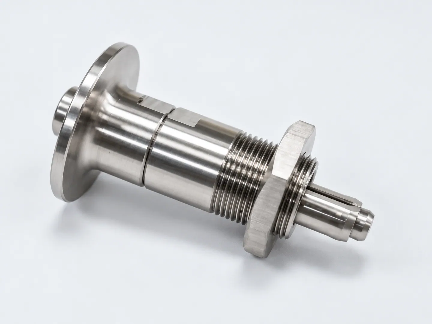
Indexing plungers & locking pins
Indexing pins require an engagement position and mounting thread. Flanged assemblies require shared bore, face and mounting-hole definitions across their components.
Request a quote for your part
- Components & artworkControlled drawings and revisions for each component, hardware list, finish and marking artwork, with assembly and test responsibilities.
- Material & orderStainless grade and condition, material records, operating environment and treatment, quantity and delivery destination.
Tell us how the part will be accepted, including measurement methods, its condition at inspection, sampling and report format.