
How to Specify Fits and Runout on Turned Parts
Specify a turned part by the surfaces that locate, rotate or seal in the assembly. Diameter limits define size; shoulder dimensions define axial location; runout relates a surface to the selected datum axis. These requirements need separate, clear callouts and an inspection arrangement that can reproduce the intended support and rotation.
On this page
Identify the working length of each fitted surface
A shaft can contain a bearing seat, seal track, coupling diameter and threaded end on the same outline. Each feature serves a different purpose. A uniform tolerance note across the whole profile can add work where it does not help and leave an important interface insufficiently described.
For each fitted diameter, identify the mating component and the length over which the fit applies. A short locating band and a long sliding interface do not necessarily need the same geometric or surface controls. Include a lead-in or edge requirement where it is needed to assemble the mating part without damage.
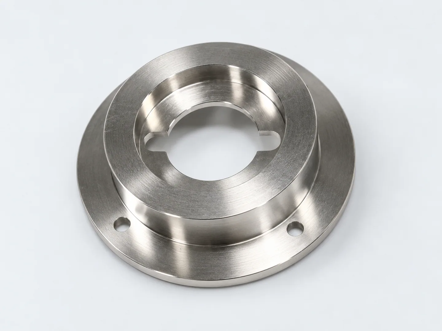
The flanged turned component brings a central bore, face and stepped outside diameters together. Its mating component determines which diameter locates the assembly and which shoulder sets the axial position. Material grade, hardness where required and final finish belong with those interface requirements.
A sleeve needs its inner and outer working surfaces considered together. The assembly may locate the outside in a housing while the bore provides a clearance or guided fit. Specify the relationship that the function needs, including relevant wall or face controls, instead of assuming that two accepted diameters automatically establish a common axis.
Diameter tolerance, circular runout and total runout
The responsible designer selects the fit and geometric controls from the assembly requirements, using the stated drawing standard. The machining supplier then reviews how to produce and measure those features.
| Drawing item | Purpose | Question to settle |
|---|---|---|
| Diameter limits | Control the allowed size of the fitted surface. | Which mating part, working length and final condition define the fit? |
| Shoulder location | Set the axial position of the seated component. | From which face or other reference is the distance controlled? |
| Circular runout | Evaluate surface variation around the datum axis at circular sections. | Which surface, datum feature and measurement locations are specified? |
| Total runout | Control the surface requirement over the specified extent under the drawing definition. | What full surface and support arrangement must the check represent? |
| Surface and edge requirements | Address contact, assembly and the required working finish. | Which roughness, lay or edge conditions matter to the mating component? |
Runout requires a defined reference axis. Hexagon’s circular-runout documentation describes evaluation in sections around that axis. The datum reference, surface extent and drawing standard still determine the actual requirement for your part.
A low runout reading taken from an unsuitable reference can be misleading. Before interpreting the value, confirm how the datum feature was established and whether the method matches the drawing. Different fixture contacts or software alignments can lead to different evaluations.
- A · Fitted journal and its surface condition
- B · Shoulder that establishes axial position
- C · Related diameter or rotating surface
Selecting a bearing-seat fit or sliding clearance
A nominal diameter does not select a fit. A bearing seat, a sliding sleeve and a removable coupling can need different allowances between their mating surfaces. The fit choice starts with how the components carry load, assemble and move in service.
SKF’s bearing-fit guidance considers rotation and load, temperature differences, and shaft or housing construction. Use the guidance for the actual bearing and arrangement when selecting its seat. A familiar fit used on another shaft may serve a different load condition.
On the machining drawing, the chosen size limits need a defined working length. The bearing or sleeve also needs to reach its seating face without fouling a shoulder radius or unfinished transition. A section showing the mating component can resolve that clearance before tools are selected.
Fit inspection and runout inspection then answer separate assembly questions. Measuring a journal’s diameter checks its size. Rotating the part about the specified datum axis and evaluating the relevant surface checks the stated runout. An accepted diameter can coexist with a runout result outside its limit, so both characteristics need their own results when both are specified.
For a treated journal, these limits apply in the stated final condition. The material and finish specification should identify the treatment and any protected working surfaces.
Consider the complete route, including milled features
A turned profile may later receive a cross-hole, flat, slot or bolt pattern. Those features need position and orientation requirements relative to the turned geometry where the assembly depends on them. A drawing that controls only the cylindrical surfaces leaves the secondary operation open to interpretation.
The supplier reviews which turned features can locate the milling setup and whether they remain accessible for holding and checking. A thread or seal track may be unsuitable as a fixture contact. Mark any surfaces that need protection and provide the complete model, rather than a drawing cropped to the turned outline.
Long or slender features also raise support questions during cutting and measurement. The production plan may need additional support, a different sequence or a review of stock preparation. The acceptance requirement should identify any specified restrained state and the surfaces that establish the datum axis.
In the turning-then-milling study, a cylindrical form receives a secondary operation. On a new part, the drawing must relate those milled features to the required axis, orientation and shoulders so the supplier can plan the locating arrangement.
A route change between prototype and repeat production should retain those requirements. If the method of holding or finishing changes, review its effect on the controlled features and the agreed checks before the batch is released.
Inspect in the required final condition
State whether dimensions apply before or after any treatment. A plated or coated fitted surface needs an acceptance requirement that accounts for the final state. If a bearing or seal interface must remain untreated, identify its boundaries and any separate protection required.
Surface finish needs a purpose. A seal track, sliding surface and visible end face can have different requirements. Where roughness or lay matters, specify the applicable characteristic and the region to which it applies. A general polished appearance note does not define a measurable working finish.
Agree how the part will be supported for runout inspection and how the reference axis will be established. Where an indicator is proposed, define the relevant measurement positions and handling of the result. Where coordinate measurement is proposed, the alignment and evaluated surface data need to suit the specified characteristic.
Sampling and records should match the order. A prototype report can establish the agreed checks, while a repeat batch needs its own release basis and identification. Retain the drawing revision, final treatment state and any approved exceptions with the measured results.
When comparing results between suppliers or receiving teams, check the method as well as the reported number. Repeating a measurement using the agreed reference and support can resolve a difference that would otherwise be treated as a machining defect.
Read a diameter result and a runout result separately
For the flanged component shown here, the bore, stepped diameters and shoulder can establish several different assembly relationships. A report headed only “shaft checked” leaves the buyer unable to tell which one was evaluated. Each controlled feature needs its result tied to the specified reference, surface extent and final condition.
If a journal passes its size limits but the specified runout fails, changing the diameter tolerance does not resolve the failed relationship. First compare the datum setup and measurement locations with the drawing. A proposed correction then needs to preserve the fit, shoulder location and any treated working surface. The circular-part datum guide covers the same alignment issue where a bore locates a mating flange.
Details to include with a turned-part inquiry
A clear drawing package allows a CNC turning review to focus on the working interfaces. Identify the dimensions that control the assembly and keep proposed changes separate from the approved requirements. If a fit is still being developed, include the mating component information and mark the unresolved decision.
- Current model and drawing, material grade and required condition.
- Fitted diameters, usable lengths, mating-component information and shoulder locations.
- Datum features and the exact geometric controls applied to each working surface.
- Cross-hole, slot or flat relationships, including angular orientation where relevant.
- Surface finish, edge condition, treatment and protected contact areas.
- Measurement setup, first-part checks and required batch records.
Keep the accepted first-part specification with later releases. A revised seal, bearing or mating housing may change what the shaft must do, even if the outer shape appears similar. Review that interface change through the drawing and inspection plan before reusing the earlier approval.