
Multi-bore circular milled component
A common centerline and mounting-face datum tie the stepped bores to the face-hole pattern. Bore fits, step depths and hole positions guide the milling plan for a circular component.
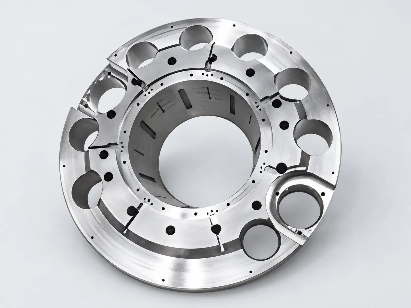
The bore steps and face-hole pattern
Each bore step needs a depth and fit. The bore center and mounting face provide the references for the surrounding holes and the relationships between them.
| Feature | Drawing requirements | Acceptance checks |
|---|---|---|
| Central opening & steps | Specify the bore diameters, step depths and mating fits from the circular face datums. | Bore diameters, depths and fits. |
| Face-hole pattern | Specify pitch-circle diameter or hole-center coordinates, hole positions, face orientation and their relationship to the central bore. | Hole positions and face orientation. |
| Additional geometry | Include the 3D model and dimensioned drawing, with mating-bore and fastener requirements. Show internal pockets in the model or section views, and define circular-face flatness and orientation from the drawing datums. | Agreed method for any additional features. |
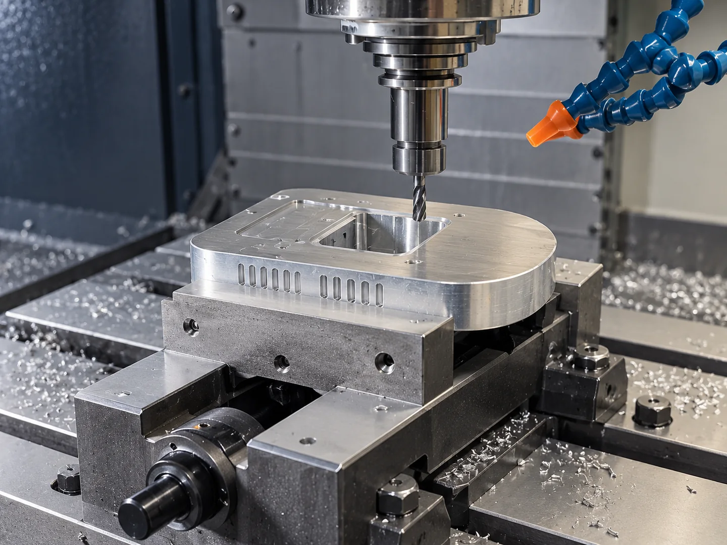
Carrying the bore datum into another setup
We check cutter access to the opening, shoulders and opposite face before deciding whether to reverse the part. If a second holding orientation is needed, we locate it from the same bore center and face reference.
Mark which cylindrical surfaces actually locate a mating part. That lets the review separate a fitted bore from a clearance opening and choose a practical way to check the hole pattern after machining.
Cutter access and common locating faces determine the proposed 3-axis, 4-axis or 5-axis milling route, including any repositioning.
Instrument, automotive and robotics assemblies require defined locating bores and mounting-hole positions. Include the mating interfaces and inspection requirements for your component.
Related machining and part forms
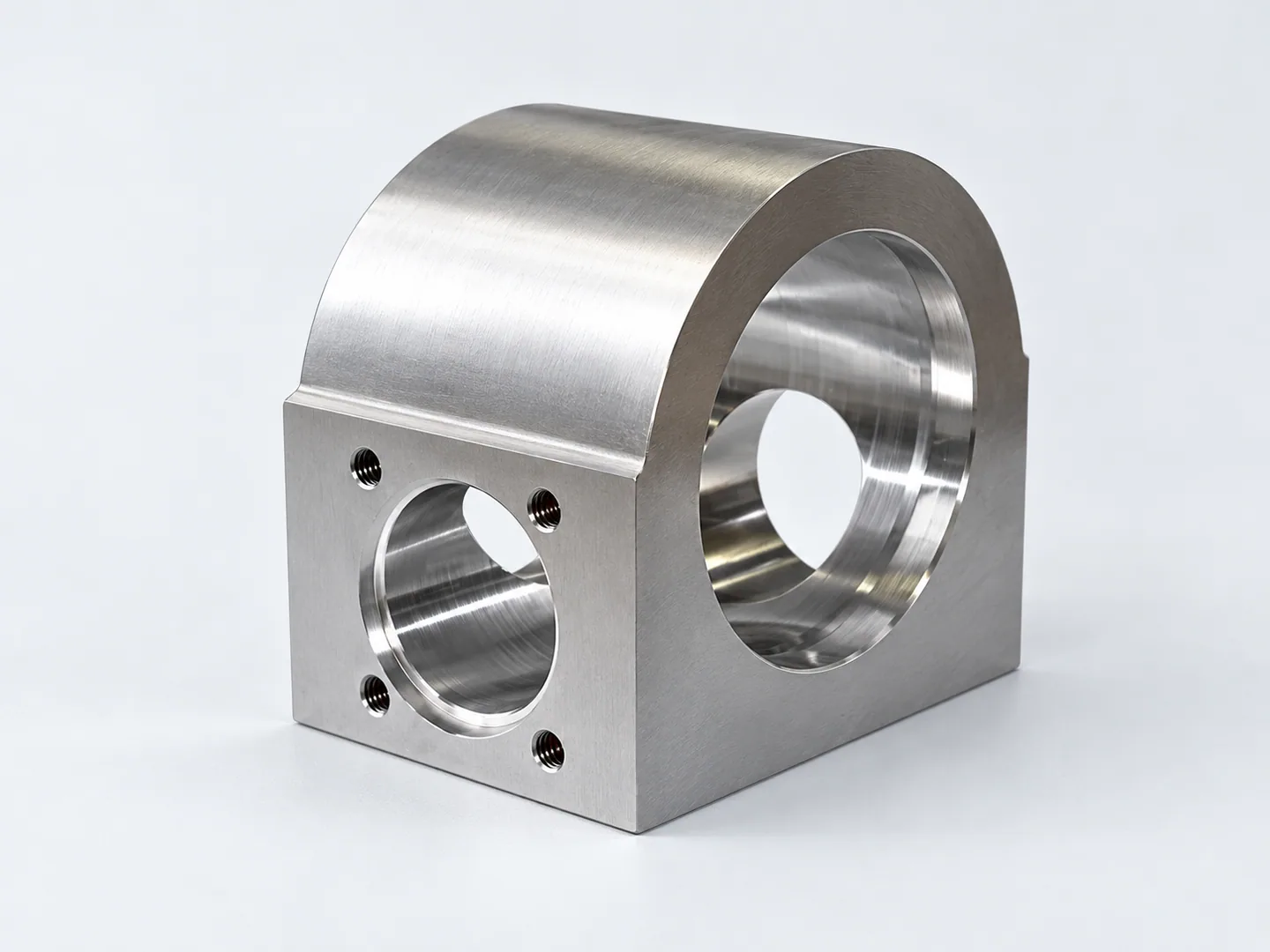
Milled instrument blocks & brackets
Compare blocks and brackets for mounting features on prismatic parts. Circular components use the bore center and mounting face to locate the surrounding hole pattern.
Request a quote for your part
- Files & datums3D model and dimensioned drawing, with the controlled revision and datum scheme.
- Mating geometryMating-bore or fastener requirements, including drawing details for any additional pockets.
- Order requirementsMaterial grade, quantity and delivery destination.
Tell us how the part will be accepted, including measurement methods, its condition at inspection, sampling and report format.