
Datums and Hole Position on Circular Machined Parts
A circular part can have correctly sized bores and holes yet fail to assemble if their locations are unrelated. Establish the functional mounting face and locating feature, then define the hole pattern and bore steps from those references. The drawing must control the relationships that matter to the mating parts, as well as the individual sizes.
On this page
Choose references from the assembly
A circular component may seat against a housing and locate on a central bore or pilot diameter. Its mounting holes may provide retention, location or both, depending on the assembly. Choose the controls from those roles; similar-looking face views can conceal different locating arrangements.
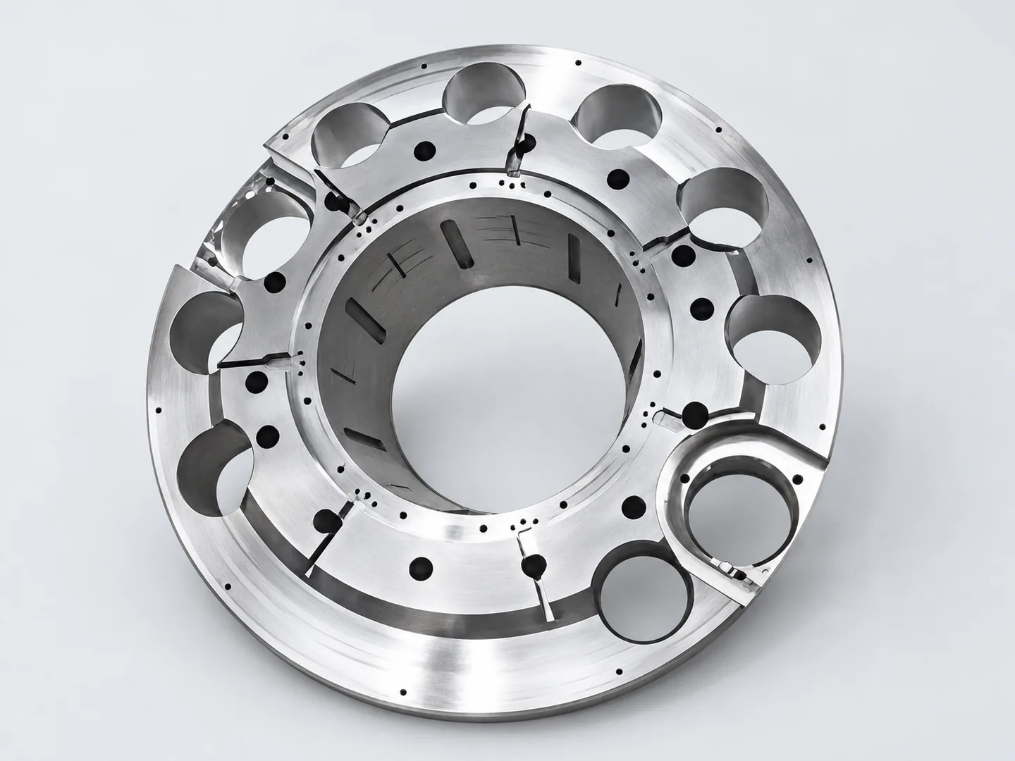
The multi-bore circular component combines a central opening, stepped bores and smaller face holes. A central bore may locate a mating pilot while the smaller holes retain the assembly. When that is the intended arrangement, the mounting pattern needs to relate to the pilot and seating face.
A useful datum scheme also addresses angular orientation when the pattern is not rotationally interchangeable. A single off-center hole, slot or keying feature may establish that orientation. Show it explicitly so the machinist and inspector do not choose different ways to clock the part.
Hexagon’s introduction to coordinate metrology explains the role of alignment in relating measured features to a reference system. The practical point for a purchasing drawing is to define that reference system before comparing reported coordinates. A different alignment can change how the same measured features are evaluated.
Hole diameter, bolt-circle diameter and hole position
A bore diameter answers whether a mating feature can fit within the specified size limits. Its location and orientation answer different questions. The same distinction applies to a mounting hole: accepting its diameter alone does not establish that a bolt pattern will align with the mating component.
| Requirement | What it addresses | Information needed for review |
|---|---|---|
| Bore size and fit | The permitted size of the mating opening. | Size limits, engagement length and the final surface condition. |
| Bore-step depth | Where an axial shoulder or component will sit. | The reference face, depth limits and the relevant step. |
| Hole-pattern position | The relationship of mounting holes to the locating features. | Datums, pattern definition and the applicable position requirement. |
| Face relationship | How the seating face relates to the locating axis or another face. | The particular orientation or runout control selected by the designer. |
| Angular location | How an asymmetric feature is clocked around the component. | An identified angular reference and its relationship to the pattern. |
Choose the geometric controls required by the function and the drawing standard in use. Do not add concentricity, position and runout interchangeably because they sound like related ideas. They evaluate different characteristics and can require different measurement strategies.
Keep the datum references and acceptance conditions next to the controlled features. A general note asking for all holes to be centered leaves too much open, especially when a component contains several circular patterns that have different assembly roles.
- A · Mounting face and axial location
- B · Hole pattern and angular orientation
- C · Central bore or other locating feature
Why the right bolt-circle diameter can still fail to assemble
PCD means pitch-circle diameter, also called bolt-circle diameter. It describes the circle on which the nominal hole centers lie. A complete pattern also needs its hole count and size, spacing or coordinates, and any required angular relationship to the rest of the part.
Consider a six-hole flange with a side port that must face a fixed direction. A six-hole pattern can have the right PCD and equal spacing yet be rotated relative to that port. The drawing needs a clocking reference when that rotation matters. With a rotationally interchangeable mating part, the required orientation may be different; the datum scheme should follow the actual assembly.
A hole also has an axis through the material. Its center at the entry face does not describe its entire orientation. Where a bolt, dowel or long mating feature depends on alignment through the thickness, the applicable position and orientation controls must cover that function under the chosen drawing standard.
A report limited to diameters and PCD can miss an angular or axial alignment problem. Evaluate the specified hole locations and relationships from the functional references. On a turned mating part, the shaft fit and runout requirements establish the corresponding axis relationships.
Investigate the assembly symptom before enlarging holes
| Assembly observation | Relationship to check | Useful information for the review |
|---|---|---|
| The pattern fits only after rotating the flange. | Clocking of the pattern relative to the side port, slot or other orientation feature. | The mating drawing and the angular reference used for inspection. |
| Individual holes accept a gauge, but the mating pattern will not assemble. | Pattern location and orientation from the locating bore and seating face. | Hole results evaluated in the specified datum alignment, alongside the size results. |
| The part seats differently when fasteners are tightened. | Contact at the seating face and the specified free or restrained condition. | The assembly contact arrangement and the support used during measurement. |
These observations guide an investigation; none identifies a defect by itself. Check the released revisions and actual locating contacts first. Enlarging a hole can change location or retention in the assembly, so a proposed correction belongs in the controlled drawing and approval record.
Preserve the relationships through machining
A circular part may be turned, milled or produced through a combination of operations. Its outer outline alone does not determine the route. Features on the front, back and circumference need a practical way to remain related after the component is repositioned.
The first machined face or diameter can help locate a later setup. The supplier needs enough material and accessible contact area to use it reliably. If that surface will be finished later, the process review must account for the change rather than assuming the original relationship will remain unaffected.
Thin rings deserve attention to support. Clamping or measuring a flexible section in a forced condition can give a different picture from its free shape. The requirement should identify when an installed or restrained state is relevant, with the agreed support reflected in inspection.
For holes inside a recess, check the complete approach for the tool and holder. A short hole can still be difficult to machine or inspect if a high surrounding wall blocks access. Supply section views and permitted internal radii where those features affect the route.
The machining sequence is then a supplier planning decision against the required drawing. Our CNC milling review considers locating surfaces, access and the geometry that remains between operations. An additional setup should be assessed through its effect on the required relationships, not treated as automatically unsuitable.
Agree what the inspection result will contain
A first-article record should identify the drawing revision, feature and method of evaluation. For a patterned component, also retain the datum alignment used to evaluate the relationship. A list of hole diameters provides little help if the actual assembly issue concerns the location of the pattern.
Coordinate measurement can support checks of several related features, provided that the setup, access and evaluation suit the requirements. Some sizes or surfaces may be better checked by another agreed method. The presence of a CMM does not remove the need to define which features will be measured and how.
If a receiving team intends to use a functional gauge, discuss it before the order. The gauge should represent the specified acceptance requirement and needs a controlled definition. Passing a convenient mating assembly is not automatically equivalent to satisfying every characteristic on the drawing.
Resolve how surface treatment affects the release condition. A coated bore, masked face and treated mounting hole may need different checks at different stages. Keep the final dimensional results distinguishable from earlier process measurements so the customer can see which state was accepted.
Put the locating bore, seating face and mounting pattern into one controlled drawing package so the inspection alignment follows the intended assembly.
A clear specification for the circular part
Before requesting production, review the component with the mating part or assembly drawing open. Trace how the part seats, how it locates radially and what prevents an incorrect angular orientation. Where a feature only provides clearance, allow the specification to reflect that role.
- The controlled model, drawing revision and applicable drawing standard.
- Functional datum features, including the angular reference where needed.
- Bore sizes, step depths and the intended mating condition.
- Hole-pattern definition and position requirements tied to the selected datums.
- Final material and treatment state, with any restricted fixture contacts.
- Inspection alignment, reported characteristics and any agreed functional gauge.
When a result does not match an assembly trial, compare the controlled requirements with the actual locating contacts before changing dimensions. The issue may concern a missing relationship, a changed mating component or a different inspection alignment. Record the agreed correction in the drawing or acceptance plan so the next release uses the same basis.