
Preparing an Impeller Model for 5-Axis Machining
An impeller machining review starts with a complete controlled model of the blades, hub and mating interfaces. The tool must reach the required surfaces while the part and fixture remain clear of the holder and machine. Define the geometric acceptance requirements separately from any balance or operating-performance tests needed for the finished component.
On this page
Supply the surfaces that define the impeller
A rendered outside image does not fully describe the passages between blades. The manufacturing model needs the approved surfaces and their transitions, including the root and the connection to the hub. Missing or inconsistent surfaces can prevent a reliable toolpath review even when the visible outline looks complete.
Confirm the units, revision and controlling file. A neutral model may be convenient for exchange, but the drawing should identify the requirements that the model alone does not state. These can include datums, surface acceptance, material condition, edge requirements and the treatment of any permitted geometry changes.
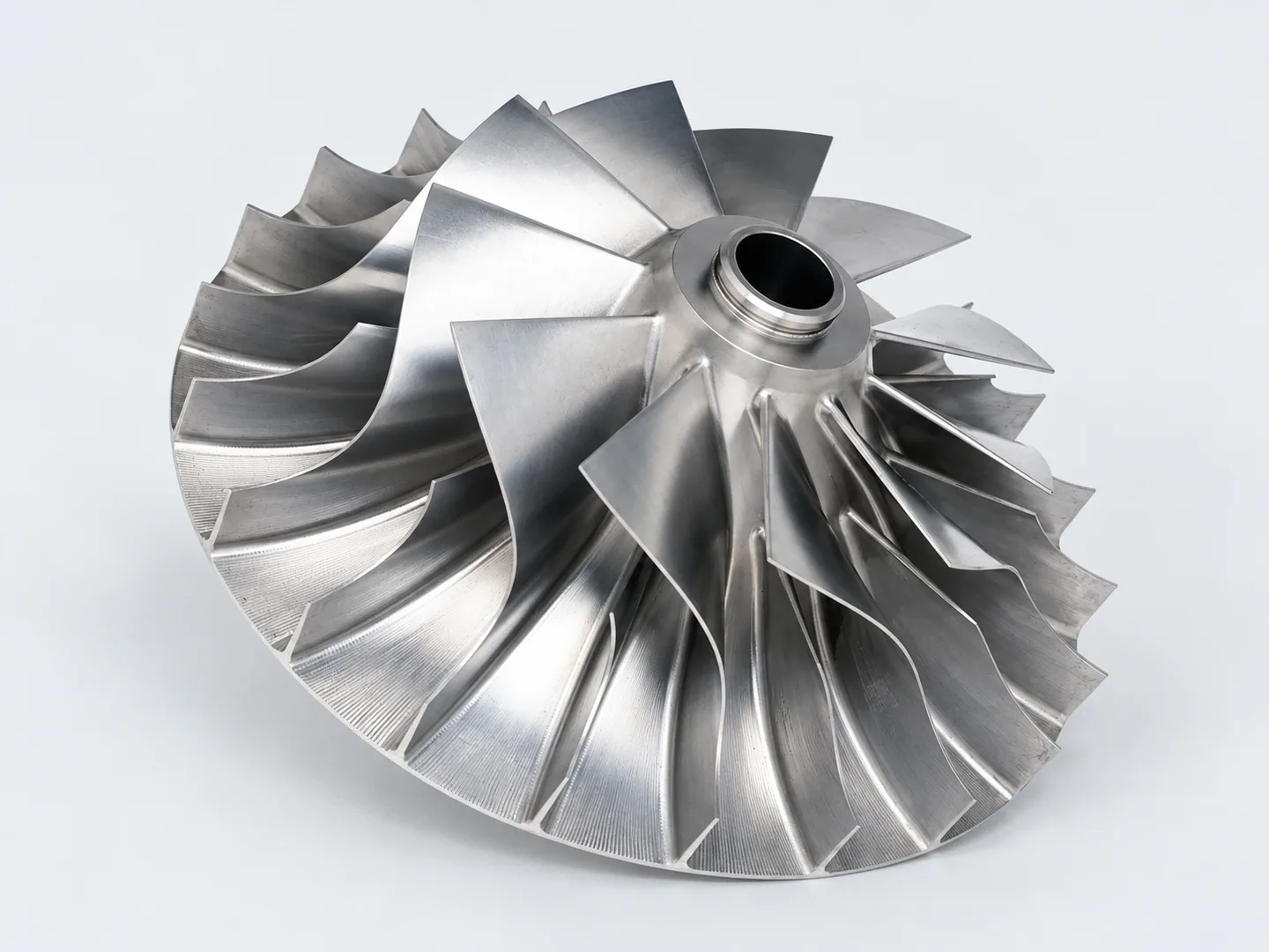
The swept-blade impeller has narrow passages around a central hub. Blade curvature, the root transition and the hub interface all affect the cutting and inspection approach. The manufacturing model needs those surfaces connected and identified under one controlled revision.
Where the design contains a family of variants, separate the part numbers and revisions. Differences in hub size, blade profile or mounting features can change both the cutting and inspection strategy. Avoid using a single reference drawing for variants whose controlled surfaces are different.
Resolve model repairs before programming
If the supplier finds a missing face or inconsistent transition near a blade root, ask for a marked view identifying the location and proposed repair. A change to a controlled blade or hub surface needs the design owner's approval. Keep the repaired file under a new identifiable revision so programming and later geometry comparison use the same definition.
A display rendering is useful for orientation, but it cannot settle a disagreement between manufacturing files. Identify which model controls the blade passages and which drawing controls the hub fit and mounting references. Where a mesh is supplied, agree whether it is an adequate manufacturing definition for the required surface and inspection work.
Tool and holder clearance between impeller blades
The cutter is only part of the space required for machining. Its holder, spindle approach, fixture and rotating workpiece also need clearance. A blade surface can be visible in a CAD view but obstructed by a neighboring blade when the tool assembly approaches at the required angle.
Sandvik Coromant’s guidance on closed pockets and angles uses blisk and impeller geometry to explain the access problem. The shape of the pocket and its bottom profile influence the required machine motion. The route for a particular impeller still depends on the complete model and proposed setup.
Passage depth, local curvature and the space at the root can restrict tool selection. If a transition is open to change, mark the permitted range or route the proposal back to the design owner. The machining supplier should not alter a controlled blade surface simply to make a tool fit.
Thin blade edges need a defined final condition. Identify any permitted edge preparation and the surfaces to which the requirement applies. An instruction to remove all sharp edges can be inappropriate when an edge is a controlled part of the aerodynamic or hydraulic design.
Review the holding arrangement at the same time. The hub or temporary stock may provide support for machining, while the eventual mounting features require a different acceptance setup. The route needs to preserve those interfaces without treating a convenient machining contact as the functional datum automatically.
- A · Blade surfaces and passage access
- B · Hub bore and mating features
- C · Blade root and permitted transitions
Choosing indexed or simultaneous five-axis impeller machining
Indexed positioning changes the part orientation between cuts. Simultaneous five-axis machining changes tool orientation during a cutting path. The difference matters when a tool needs to follow a curved blade surface while maintaining clearance from the next blade and the hub.
The presence of blades alone does not settle that choice. An accessible surface may be cut from a fixed orientation, while a deeper passage or a swept region can require a changing approach. Tool length, holder diameter and the fixture also affect which orientations are practical.
A useful CAM review includes the complete tool assembly, workholding and stock at each stage. Clearance at the start of a path is insufficient if the holder approaches an adjacent blade farther along it. Machine travel and rotary limits belong in that review as well.
Use the approved model to identify fixed surfaces and transitions open to a design proposal. Simulation can then assess the proposed route, with finished geometry checked against the inspection requirements. The machining process comparison covers indexed and coordinated motion on other part forms.
Blade profile, blade-root and hub inspection requirements
A drawing can control the blade geometry and the connection to the rest of the assembly in different ways. Identify the characteristics that require a report, and agree which regions and features will actually be evaluated.
| Feature | Design information | Inspection question |
|---|---|---|
| Blade surfaces | Approved profiles, model revision and applicable geometric limits. | Which surfaces and regions are compared with the controlled model? |
| Blade roots | Transition geometry and any permitted local changes. | How can the root regions be reached and checked? |
| Hub bore | Fit, reference features and the mating component. | Which size and relationship checks define acceptance? |
| Mounting face or features | Axial location and required relationship to the hub. | What datum setup will evaluate the specified orientation or runout? |
| Working edges | Defined final profile and permitted edge condition. | How is edge condition distinguished from general deburring? |
A scan or coordinate measurement needs an agreed relationship to the drawing. Selecting an alignment that makes an overall color plot look favorable is not a substitute for evaluating the specified datums and controlled regions. Identify how the reported results will demonstrate the required geometry.
Some areas may be difficult to measure directly with the proposed equipment. Resolve those limitations during review and agree an appropriate method. Do not wait until the part is complete to discover that the required root or passage characteristic cannot be evaluated as specified.
For an initial impeller, agree the reported regions before the sample is machined: the hub interface, the specified blade surfaces and the root regions that need evaluation. A toolpath simulation addresses the proposed cutting route. It does not replace those finished-part results or any separately ordered balancing or operating test.
Keep material, balance and performance requirements identifiable
The material specification needs the alloy, condition and any required defect criteria. Required heat treatment or other processing must have a defined place before the relevant final geometric checks. Material records should remain attached to the accepted part or batch identity.
Dimensional conformity, balancing and operating performance are separate acceptance activities. If balancing is included, define the applicable requirement, configuration and responsibility, including whether it concerns the individual component or a larger rotating assembly. The supplier must confirm the actual scope it can provide.
Flow, pressure, efficiency or endurance requirements need a suitable test definition and responsible party. They cannot be inferred from a machined blade finish or a model comparison. State which tests are part of the order and which will be performed later by the customer or another qualified provider.
A proposed change at the root, edge or hub goes back to the design owner because its effects can extend beyond machining. Record the approved geometry in the production revision. Our five-axis machining review uses that revision to assess surface access and the checks required on the finished part.
Prepare the impeller review package
A useful quotation package brings the surface definition and acceptance requirements together. Identify what is fixed and which features may be discussed for manufacturability. That allows the supplier to distinguish a machining question from a request to redesign the component.
- Complete controlled model, drawing, units, part number and revision.
- Material grade, condition, treatment and required records.
- Blade profiles, root transitions, hub fit and mounting requirements.
- Protected surfaces, permitted edge preparation and any approved geometry allowances.
- Inspection datums, reported regions, methods and first-part acceptance.
- Separate balance or functional-test requirements, supplied configuration and responsibility.
- Quantity and the basis for any later repeat release.
For an initial sample, record the accepted model revision and the completed checks before releasing a batch. If the design or supplied configuration changes, review which measurements or separate tests need to be repeated. Keep the production approval attached to the requirements that were actually checked.