
Choosing Thread and Seal Requirements for Machined Fittings
A machined fitting needs a defined connection at each end and a clear description of where sealing takes place. Nominal thread size alone leaves the standard, engagement and sealing arrangement unresolved. Specify the complete end connection, its mating component and the separate acceptance requirements for geometry and fluid integrity.
On this page
Identify the complete connection at each end
An adapter can join two different connection systems. Record both ends separately, including the thread standard, size, pitch or threads per inch where applicable, and any required class or tolerance. State whether each thread is internal or external and identify the applicable drawing specification.
Thread identification starts with the mating connection. Two threads can look similar while differing in pitch, form or taper. A sample is useful for measurement, but the replacement needs a confirmed connection designation and the corresponding seal arrangement.
For a fitting without a controlled drawing, Swagelok’s thread and end-connection identification guide provides a procedure and reference tables for straight and tapered threads. Identifying the thread is one step toward specifying the complete connection and its seal.
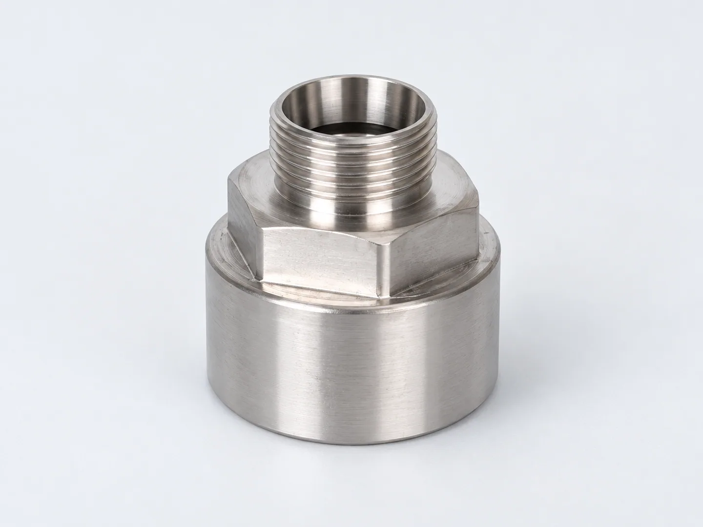
The turned connector has a threaded neck, a shoulder and wrenching flats. Those features serve different roles: the flats provide installation access, the thread retains the connection, and the specified interface determines where sealing occurs. Pressure rating and service compatibility need their own approved requirements.
Show where the seal is created
Some connections use the thread engagement as part of their sealing arrangement. Others use the thread to retain parts while a gasket, O-ring or another interface creates the seal. That difference changes which surfaces and dimensions need particular attention.
Swagelok’s explanation of fitting types describes this distinction between straight-thread retention with a separate sealing element and tapered-thread sealing arrangements. The selected connection specification and its approved assembly instructions control the actual seal and any installation requirements.
| Connection feature | Requirement to identify | Acceptance question |
|---|---|---|
| Threaded end | Standard, size, tolerance and usable engagement. | Which specified gauge or inspection method establishes conformity? |
| Face or shoulder seal | Mating geometry, surface condition and contact region. | How will the relevant size, orientation and surface be checked? |
| O-ring groove | Controlled gland geometry and selected sealing element. | Are groove dimensions and installation edges defined for the application? |
| Internal passage | Bore geometry, intersections and required cleanliness. | Can internal edges and the required condition be inspected? |
| Wrenching or mounting feature | Access, size and relationship to other interfaces. | Will the part be installed without contacting a protected surface? |
Keep sealing requirements tied to the intended fluid, temperature and service conditions. A general instruction to make the fitting leak-free does not define a test. Avoid selecting groove dimensions or surface limits from an unrelated seal example; they need to match the chosen sealing system.
- A · Thread form, standard and engagement
- B · Specified seal interface and working surface
- C · Internal passage and intersecting-hole edge
NPT, BSPT and BSPP are different connection specifications
A note such as quarter-inch pipe thread leaves the connection unresolved. NPT, BSPT and BSPP are distinct designations, and matching the nominal size is insufficient for interchangeability. A controlled replacement needs the standard and complete end-connection identity.
Parallel-thread connections can use a sealing washer, O-ring or another specified interface separate from the thread. The drawing then needs the shoulder, counterbore or gland that the selected seal uses. The thread designation by itself does not define those features.
An adapter should describe each end independently. For example, one end may connect to a selected pipe-thread port while the other uses a parallel thread and a face seal. A section through both ends shows the passage, sealing contacts and available engagement without relying on the outside profile.
For an O-ring arrangement, the selected seal and gland specification control the groove and entry edges. A sharp intersecting edge or an undefined lead-in can create a different problem from thread fit. Seal-material compatibility and any leakage test remain part of the application specification.
Cross-drilled passages, internal burrs and cleaning
Cross-drilled holes and intersecting passages can leave internal burrs. Those edges may affect assembly, cleanliness or the passage itself. Their location matters because an edge that can be reached directly is different from one hidden behind a thread or a long narrow bore.
Provide a section or a complete model for internal geometry. Identify dead ends, step changes and the surfaces that must remain free of unwanted material. If a passage will later be plugged, define the plug, closure method and responsibility for checking the completed condition.
A small fitting can also be difficult to hold after most of its material has been removed. Thin walls between a thread and a bore need review against the complete geometry. The machining plan must protect working surfaces while leaving access for the tools and the agreed checks.
Specify the edge condition needed by the application. A broad instruction to break every edge can conflict with a sealing land, a controlled thread start or a thin feature. Mark exceptions and identify which internal intersections need a particular inspection.
When cleanliness is important, describe the required condition and verification method. Visual inspection of an external surface cannot represent the state of every internal passage. The quotation should identify the cleaning and checking work actually included for your part.
Agree dimensional inspection and any leak test separately
Thread gauging, dimensional checks and leakage testing answer different questions. A conforming thread can still be assembled with an unsuitable seal or damaged mating surface. A completed leakage test, in turn, does not replace checks of every size and feature on the drawing.
If leakage or pressure testing belongs to the order, the responsible engineer needs to define the procedure and acceptance criteria. The test configuration, medium, pressure or other relevant conditions, duration and permitted result should be recorded with the supplied-item scope. The supplier must confirm capability for that specified test before it is included in the quotation.
Identify whether the delivered item is a machined body, a fitting with selected seals, or an assembled and tested connection. A supplied seal should have its own controlled specification. Do not assume that a sample assembly establishes the approved configuration for a later batch.
Material condition and any coating also affect the final drawing review. State the required material records, treatment boundaries and acceptance state of the threads and sealing surfaces. Any post-machining treatment needs to be included when agreeing the final checks.
During a turned-fitting review, we check tool access and secondary milling alongside the connection requirements. Resolve open thread or seal details in the quotation review; choosing either later can change the part being supplied.
Make the test configuration match the supplied connection
A test that closes a passage at a different interface may leave the customer's seal outside the test boundary. The test instruction therefore needs a section or assembly view showing the installed seals, plugged ports and surfaces exposed to the test medium. That configuration belongs with the procedure and acceptance criteria already agreed for the order.
Also distinguish the machined body from the completed fitting. One quotation may cover a body with gauged threads, while another includes specified seals, assembly and an agreed leakage test. Compare those deliverables before comparing unit prices. A successful test of an earlier sample applies to its recorded configuration; a later seal, coating or mating-port change needs review.
A fitting specification ready to quote
Use a separate line or drawing detail for each connection. If the fitting is replacing an existing component, keep measured observations distinguishable from confirmed specifications. A critical connection needs an approved definition before a sample is used to release production.
- Part number, controlled model and drawing revision.
- Complete thread and end-connection identity at each end.
- Material grade, condition and any required treatment or records.
- Seal arrangement, mating component and controlled seal geometry.
- Passage sections, internal-edge requirements and cleanliness criteria.
- Dimensional acceptance, specified gauges and any separately agreed functional test.
- Body-only or assembly supply, included seals or plugs, quantity and identification.
Send the drawing with the quantity, destination and supplied-item list in the RFQ package. Keep the thread, seal and test requirements on the drawing or its controlled specification so machining, assembly and receiving inspection work to the same definition.