
Material & finish for CNC parts
A bore, sealing face or electrical contact may need a different treatment from the outside surface. Specify each working interface so material, machining, finishing and inspection all refer to the required finished condition.
On this page
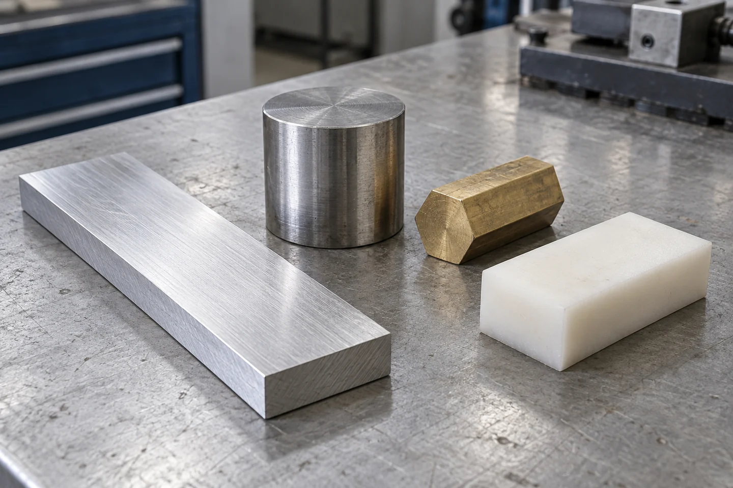
Choose the material specification
Material selection starts with the job the part performs. Loads, temperature, chemical exposure and the mating component help narrow the choice. Electrical contact, thermal transfer and cleanliness can be just as important as mechanical strength.
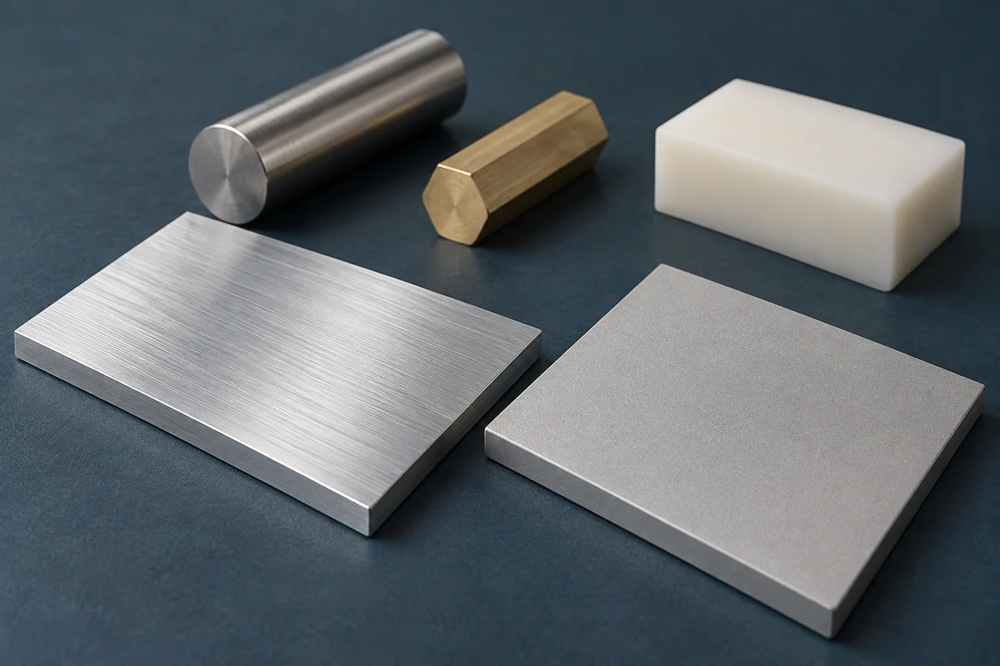
For each material family, settle the exact grade, condition, product standard and availability. The order also needs material records and an approval process for substitutions.
| Material family | Material examples | Order specification |
|---|---|---|
| Aluminum | 6061, 7075, 2024 | Alloy and temper; strength, stiffness, weight, environment and finish. |
| Stainless steel | 304, 316, 17-4PH | Service environment, strength, condition and heat treatment. |
| Copper and brass | Exact designation required | Electrical, thermal or mechanical function and applicable material standard. |
| Engineering plastics | POM, PEEK, PPSU | Temperature, load, chemical exposure, electrical needs and mating material. |
| Other named materials | Titanium, Inconel, Kovar, Invar | Exact designation and intended use for review. |
C3600, H62 and C36000 are separate alloy designations. Specify the exact grade and standard for the order.
For aluminum, the 6061 and 7075 selection guide separates strength, stiffness, temper and finish. For other families, use the stainless-steel, copper and brass and engineering-plastics pages to discuss the intended function and exact requirement.
Choose surface treatments by function
Set each finish requirement by function: appearance, wear, corrosion protection or another specified duty. Define color, coating thickness and sealing-face acceptance separately.
Deburring, polishing, blasting, anodizing, passivation or plating depend on material and order requirements. Confirm the specification before production and inspect at the agreed stage. State any sequence requirements where one treatment follows another.
- Process and specification
- State treatment, applicable standard and revision, coating thickness and measurement method. For anodizing, specify alloy and color; for passivation or plating, identify the process specification.
- Appearance
- Identify cosmetic faces, color, gloss, texture and agreed visual acceptance references, including blast or polish references where needed.
Define the surface where the requirement applies
A part can contain a visible outer face, a hidden mounting face and a precision bore. Giving all three the same blanket note may create work or ambiguity without helping the assembly. Mark the surfaces that need the treatment and the exceptions that matter.
If a general finish applies to the whole part, make the local exceptions easy to identify. The drawing should let machining, finishing and inspection find the same face without relying on an informal email description.
Dimensional changes and fits after finishing
Acceptance should describe the condition that enters the assembly. A part that meets a dimension before treatment may not meet it afterwards. State whether the limits apply before or after treatment, then agree how the machining allowance and final check will be handled.
For anodizing, oxide forms partly within the original surface and partly beyond it. The Aluminum Anodizers Council FAQ explains that the dimensional effect depends on alloy and process. Its nominal relationships differ between Type II and hardcoat conditions, and surface preparation can also affect size.
| Feature | What can change | What the drawing should resolve |
|---|---|---|
| Outside diameter or raised face | Outward build can increase the finished size. | Final size limits, treatment and the agreed machining allowance. |
| Bore or internal slot | Build on opposing surfaces can reduce the opening. | Finished opening, coating or masking and the inspection stage. |
| Thread | Treatment can affect functional engagement and gauging. | Thread designation, treated or masked condition and final checks. |
| Sealing or sliding face | Texture, local build and treatment edges can affect contact. | Functional area, surface requirements and permitted treatment boundaries. |
| Electrical contact | A treated surface may behave differently from bare material. | Contact area, required conductivity and compatible protection. |
A simple allowance example
Suppose a reviewed finishing process predicts 10 micrometres of outward growth on each exposed surface. An outside diameter would increase by about 20 micrometres, while a bore coated on both sides would lose about 20 micrometres of opening. This is an illustration using an assumed growth value, not a coating specification or a machining instruction.
Total coating thickness and outward growth are different values. Agree the process-specific machining allowance, expected variation and final acceptance limits before cutting a precision fit.
Small internal features need their own review
Coating coverage inside deep or narrow openings needs a separate review. NASA/JSC’s anodizing process specification discusses this issue for hard anodizing and the relationship between machining and final dimensions. Identify the applicable process specification on the order.
For a critical bore, identify where it is measured and whether uniform coverage is required. Resolve masking, post-treatment machining or another approved route before production. Each option changes which material is exposed and what needs inspection.
Masking bores, threads and electrical contacts
Masking is a design choice for a particular surface. It may preserve a fit or contact area, but it also changes where the specified treatment is present. The decision needs the fit, environment and protection requirements together.
Mark the actual boundaries. “Mask critical areas” leaves the finishing supplier to decide which faces are critical, how far the mask extends and what is acceptable at its edge. A section view or a clearly identified surface can resolve a small internal feature more effectively than a general note.
Threads need a finished acceptance condition
Specify the thread designation, class, depth and functional requirements. State whether the thread is treated, masked or completed after treatment, and set the final gauging condition.
Chasing or cutting a thread after treatment can expose base material. Where that affects corrosion protection or cleanliness, the drawing and process review need to resolve it. A repair or rework should not become an undocumented shop decision.
Electrical contacts are local working surfaces
Identify current-carrying or grounding faces and their contact-area requirements. State the mating material, permitted protective treatment and assembled condition used for acceptance.
Keep permitted rack or contact-mark locations separate from the electrically functional area. Where marks would affect appearance or fit, agree an acceptable location and inspection reference.
On an aluminum locating bore, the masking boundary and final anodized condition should include the entry chamfer and adjacent shoulder where they affect the fit. This gives machining, finishing and receiving inspection the same surface definition.
Surface roughness and appearance need different checks
Functional roughness needs a parameter and measurement conditions. Form and waviness have their own controls; color, gloss and permitted defects need separate limits where they affect working or visible faces.
For roughness, name the parameter, units, limit and applicable standard. Include the measurement area and conditions where they affect acceptance. The drawing guide’s roughness section explains why Ra, Rz and the measurement method need to stay connected.
Surface preparation remains part of the result
Surface preparation affects the texture after anodizing, as described in NASA/JSC's process specification. Where a visible face requires blasting or polishing, define the preparation sequence and appearance acceptance before anodizing.
Identify the material, preparation and treatment represented by the appearance sample. Agree viewing conditions for color, gloss and permitted marks, and retain the approved sample with the order records for repeat batches.
Finishing stainless steel, copper, brass and plastics
Stainless steel: passivation is not decorative plating
Passivation treats the stainless surface and removes contamination such as free iron. Carpenter Technology’s passivation guidance explains the grade-specific process and testing requirements. Specify any required corrosion verification separately from surface appearance.
Specify the stainless grade, condition, treatment standard and required verification. State the sequence where heat treatment or another operation precedes passivation.
Copper and brass: define the working contact
For electrical or thermal components, identify the contact faces and protected surfaces. Specify the substrate and plating separately, with distinct acceptance requirements for conduction and appearance.
Plastics: include the condition in which size matters
Polymer grade, temperature and moisture condition can influence the measured part. Ensinger’s dimensional-stability guidance distinguishes thermal expansion and moisture uptake, which vary between materials.
For a plastic component fitting into a metal assembly, state the service environment and inspection condition. A dimension checked just after machining may not describe every later condition. Review the exact polymer and any conditioning requirement instead of assigning the same behaviour to all engineering plastics.
The machined plastic measurement guide explains how to specify temperature, conditioning and support so the supplier and receiving team assess the fit in the same material state.
Solid plastic, surface coatings and separate coverings
A solid plastic part uses the specified polymer throughout. A coated metal part has a separate surface treatment; a covered wheel or roller has a separate covering as part of the component. Those constructions need different material and dimensional definitions.
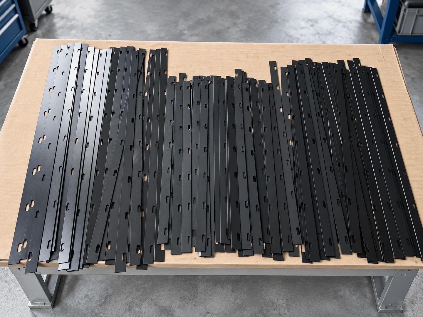
The Teflon surface-coating collection shows coated round components and long pieces with repeated holes. These use a coated substrate; parts machined from solid PTFE have a different construction.
Coated surfaces, holes and mounting faces
On a round coated part, distinguish the outside working surface from the bore and mounting faces. For a long component with repeated holes, specify whether coating enters the holes and identify the mating contact areas. Keep those requirements in the controlled drawing and finishing specification.
Specify the substrate, coating and surfaces to treat or mask. State whether critical dimensions apply before or after coating, with thickness, adhesion and service requirements. For a separate covering component, include its material and retention method.

Finished interfaces on a pocketed enclosure
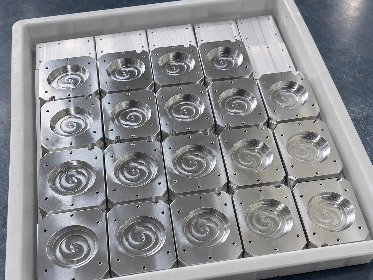
The pocketed enclosure study shows recessed parts and an associated machining setup. For a new design of this form, follow the assembly surfaces through the planned finish.
A mounting face can locate the housing, while a bore may locate another component. A cover interface can need flatness and a defined texture, whereas the exterior may mainly need an appearance requirement. Specify each face separately so its finished condition can be checked.
Follow one interface through the process
For a locating bore, the finished fit and datum relationship come first. The treated or masked condition determines the machining allowance, final measurement and records. If cutting after finishing is proposed, check the resulting exposed material and protection before accepting the route.
Use the machining study to review geometry and setup access. The process-selection guide explains how the required faces determine the machining sequence; specify the finish and acceptance criteria for your part.
Separate the lid rim from the clearance cavity
On a pocketed aluminum housing, the closure rim, locating openings and cavity walls can have different jobs. Put the selected treatment and final dimensional requirement on the actual working region. A color requirement on the outside does not identify how a fitted bore or sealing rim will be accepted.
When comparing a finish proposal, ask which surfaces receive preparation, which remain masked and which results accompany the finished part. An appearance sample for one alloy and preparation cannot establish every dimensional or visual requirement for a changed material and route.
Edges, cleanliness and packing affect the delivered surface
A general deburring note can leave important details unresolved. Identify edges that need a defined break, edges that must retain their shape and internal intersections where loose burrs would affect function. Where the drawing requires a radius or chamfer, name it explicitly.
Surface acceptance should also address handling. A sliding face or cosmetic panel can meet the requirement after finishing and still be damaged before delivery. Define separation, protection of threads and seals, and any cleanliness requirement with the packing scope.
Keep rework and touch-up visible
Agree the disposition of damaged surfaces or out-of-limit fits against the drawing and order. Record any permitted polishing, stripping, re-coating or touch-up work, including its effect on the finished requirements.
The packing and shipping guide covers protection and delivery responsibilities. Use it alongside the finish definition when the surface is part of acceptance.
Material, treatment and dimensional records
Include material traceability and treatment records in the quotation, along with dimensional inspection and any other tests. State the test limits and sampling requirements. The documents should identify the part, drawing revision and batch.
Before production, confirm that certificate scope meets the customer or industry requirements, then agree the available report format and traceability chain.

| Record or check | What it should relate to |
|---|---|
| Material record | Specified grade, condition, applicable product requirements and agreed traceability. |
| Treatment record | Process specification and revision, part or batch reference and required results. |
| Dimensional inspection | Critical interfaces checked at the agreed stage, with drawing revision and results. |
| Appearance approval | Representative reference, identified faces and agreed viewing and acceptance conditions. |
| Release decision | Actual approval, unresolved items and any accepted deviations or rework. |
Request separate records for material, treatment and dimensional acceptance. Identify the finished bores and coating requirements that each report must cover.
Material and finishing questions
Can I subtract coating thickness to find the machining size?
Not without reviewing the process. Total coating thickness and outward growth are different quantities for anodizing. Opposing surfaces, preparation and local coverage also matter. Agree the allowance and variation for the actual feature and treatment.
Will anodizing remove milling marks?
It should not be specified as a way to erase them. Establish the required preparation and finished texture before treatment. If a face must be blasted or polished, define where that applies and how the final appearance will be accepted.
Does a coating certificate prove the final fit?
A certificate confirms only the work and results within its agreed scope. It establishes a finished fit only if that scope includes the relevant dimensional evidence. Identify which interfaces need measurements after treatment and which records accompany the order.
What if the material or finish is not yet decided?
Send the part function, model and drawing with the known loads, exposure and interfaces. Identify the open choice and any options you would like reviewed. Keep proposed alternatives separate until the material, treatment and acceptance conditions are approved.