
CNC drawings & critical features
Faces and holes that locate, mate, seal or carry load need measurable requirements, references and a specified inspection condition. The worked plate follows three drawing callouts through example readings, including a failed dimension that prevents release.
On this page
Connect the drawing to the working interfaces
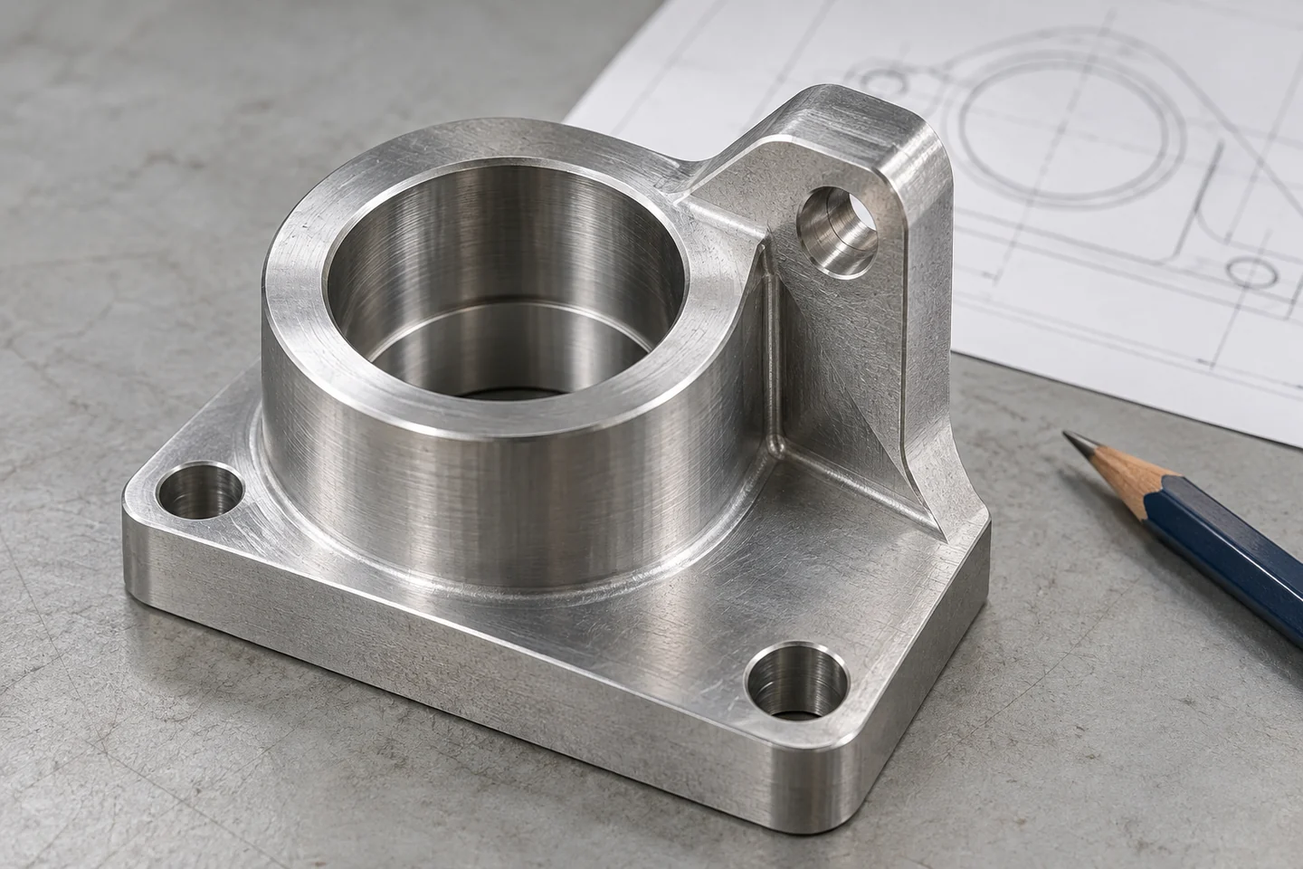
A locating bore and an outer clearance face do different jobs. Their limits should reflect that difference. Mounting faces, shaft seats, sealing lands and sliding surfaces often need both a size requirement and a relationship to the features around them.
The responsible design engineer selects the datum scheme, tolerances and drawing standard. ASME Y14.5 provides a language for geometric dimensioning and tolerancing on drawings and digital models. Naming the applicable system and revision avoids mixed symbols and conflicting defaults.
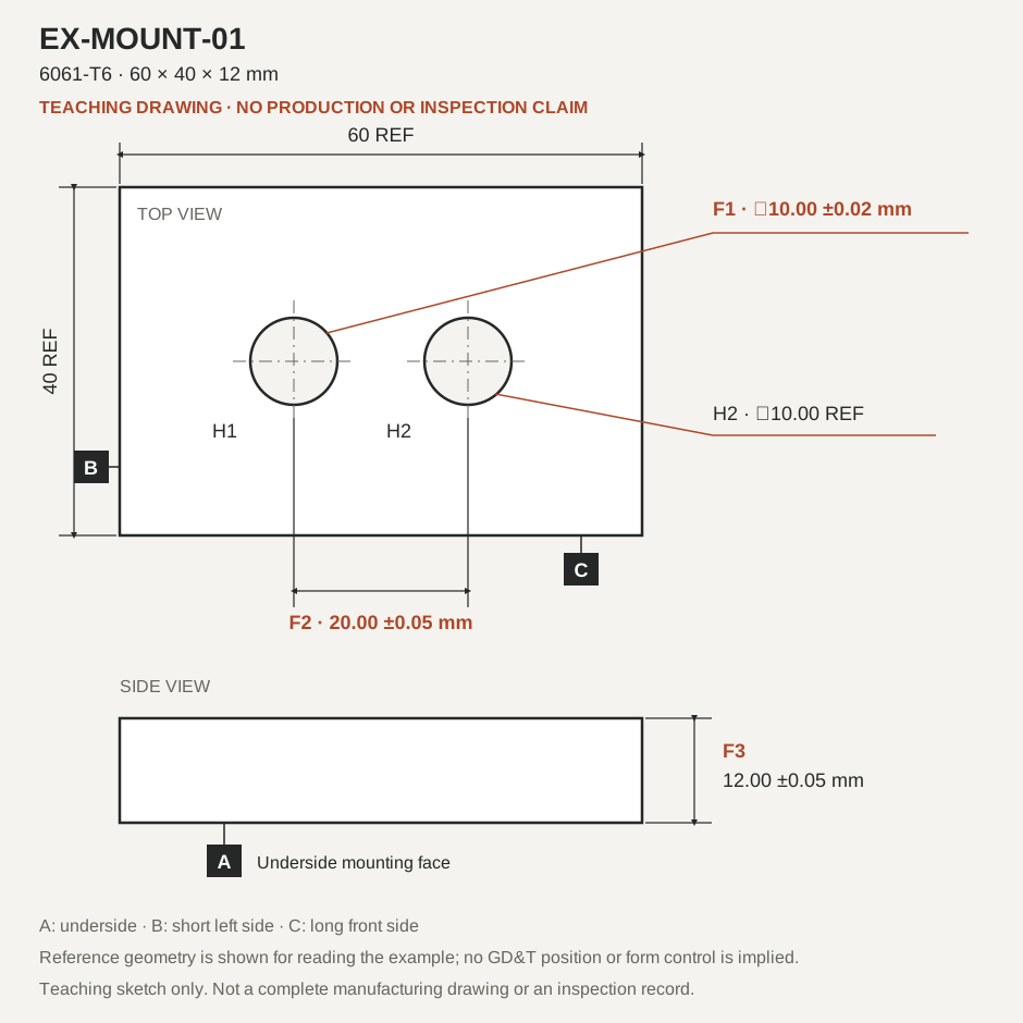
In EX-MOUNT-01 below, the underside A supports the plate and side faces B and C locate it. F1 identifies a bore size, F2 a centre distance and F3 a thickness. These references connect the sketch to its teaching inspection sheet; they do not make it a complete production drawing.
Worked example · EX-MOUNT-01
From drawing callout to inspection result
Teaching example only. All measurement values are illustrative, not LZZ production or inspection records.
A 6061-T6 mounting plate, 60 × 40 × 12 mm, connects the three feature references below to the same example inspection sheet. The material is assumed for the exercise; a real assembly needs its own load and material assessment.
Read the feature references
- F1 · H1 bore diameter
10.00 ±0.02 mm. Controls the size of the illustrated locating hole.
A bore-size measurement checks this limit. It does not establish hole form or location.
- F2 · H1 to H2 centre distance
20.00 ±0.05 mm. Controls the illustrated spacing between the two hole centres.
Evaluate both hole centres in a consistent setup. This size check is not a complete position tolerance.
- F3 · Plate thickness
12.00 ±0.05 mm. Controls the distance from the underside mounting face to the opposite face.
Measure in the stated final condition, then compare the reading with both limits.
Compare the illustrative results with the limits
All values are in mm. The illustrative readings compare numerical limits in the final machined condition before surface treatment. The exercise covers these three dimensions only; measurement uncertainty and production acceptance decision rules are outside its scope.
| Feature | Requirement | Allowed range | Illustrative reading | Result |
|---|---|---|---|---|
| F1H1 bore diameter | 10.00 ±0.02 mm | 9.98 to 10.02 | 10.01 | Pass |
| F2H1 to H2 centre distance | 20.00 ±0.05 mm | 19.95 to 20.05 | 20.03 | Pass |
| F3Plate thickness | 12.00 ±0.05 mm | 11.95 to 12.05 | 12.08 | Fail |
Hold release: F3 is outside its illustrated limit. The two passing readings do not override the failed thickness check. In a real order, the affected part would remain on hold while the discrepancy and disposition are resolved.
Turn each working feature into a checkable requirement
| Feature | Drawing requirement | Inspection consequence |
|---|---|---|
| Locating faces and axes | The references and relationships needed by the assembly. | The part must be located consistently for the stated check. |
| Bores and shafts | Sizes, limits and any applicable fit requirement. | Recorded dimensions or a specified functional-gauge result. |
| Hole patterns and slots | Location and orientation relative to the selected references. | A method that evaluates the required relationship. |
| Sealing and cosmetic faces | Surface requirements on identified faces. | Texture checks or the specified appearance reference. |
| Threads and edges | Thread designation, usable depth and local burr or edge limits. | Checks that can reach the actual feature. |
| Treated surfaces | Coated or masked areas and the stage at which limits apply. | Pre-treatment and final checks kept distinct. |
Use a balloon or feature number to link each drawing callout to a report row. The example uses F1/F2/F3. Inspection frequency is a separate requirement: one example reading, a sampled batch report and a check on every part cover different scopes.
Datums across setup changes
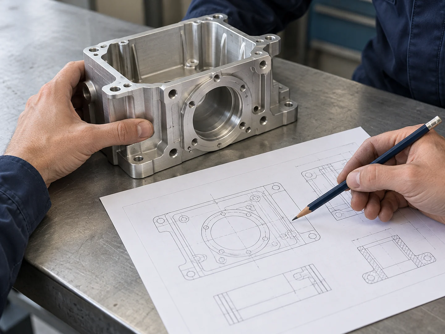
Assembly function establishes the drawing references. A fixture may use its own process references, but finished acceptance still follows the drawing. A bore and mounting face made in different orientations need their required relationship carried across both operations.
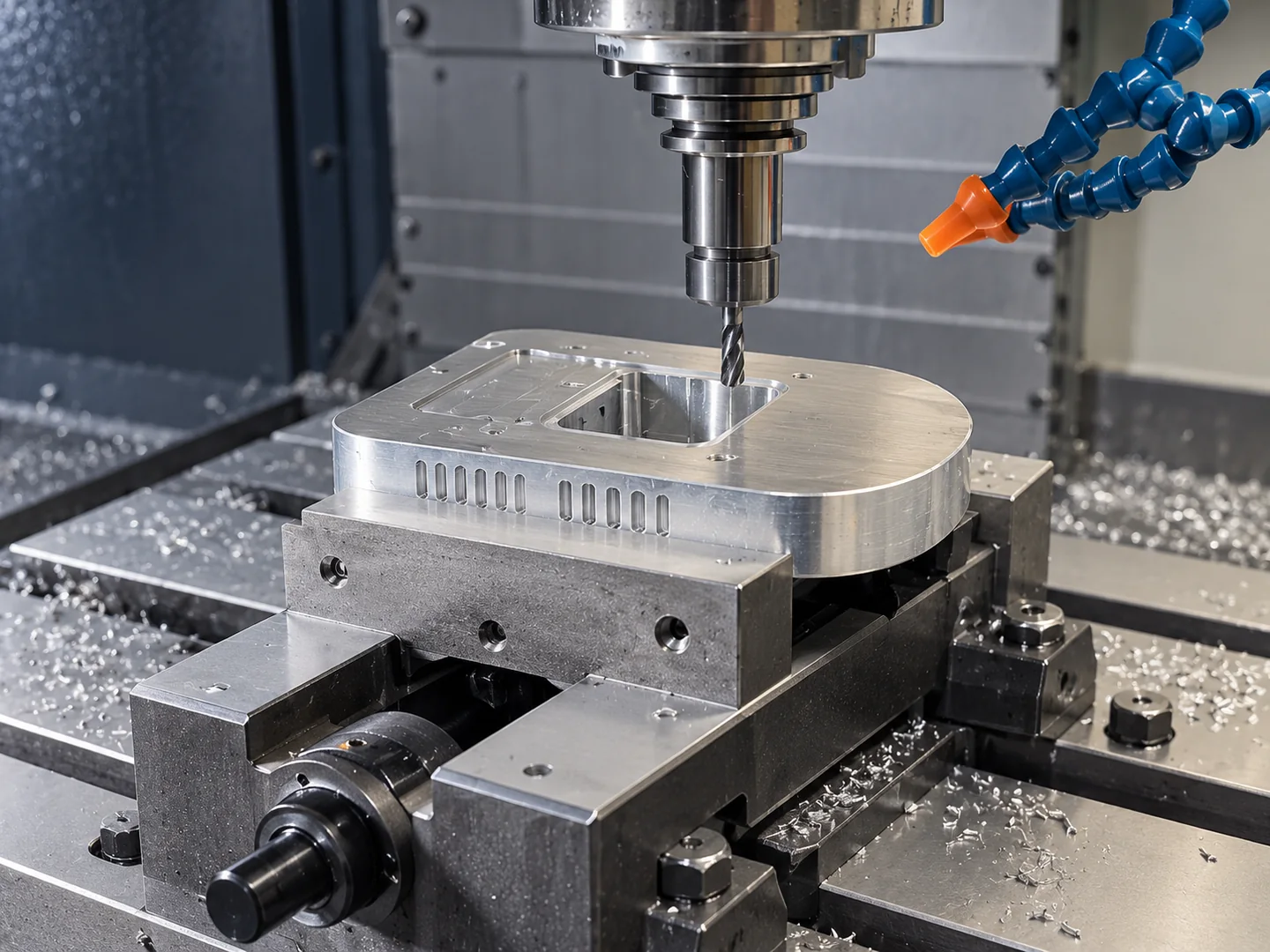
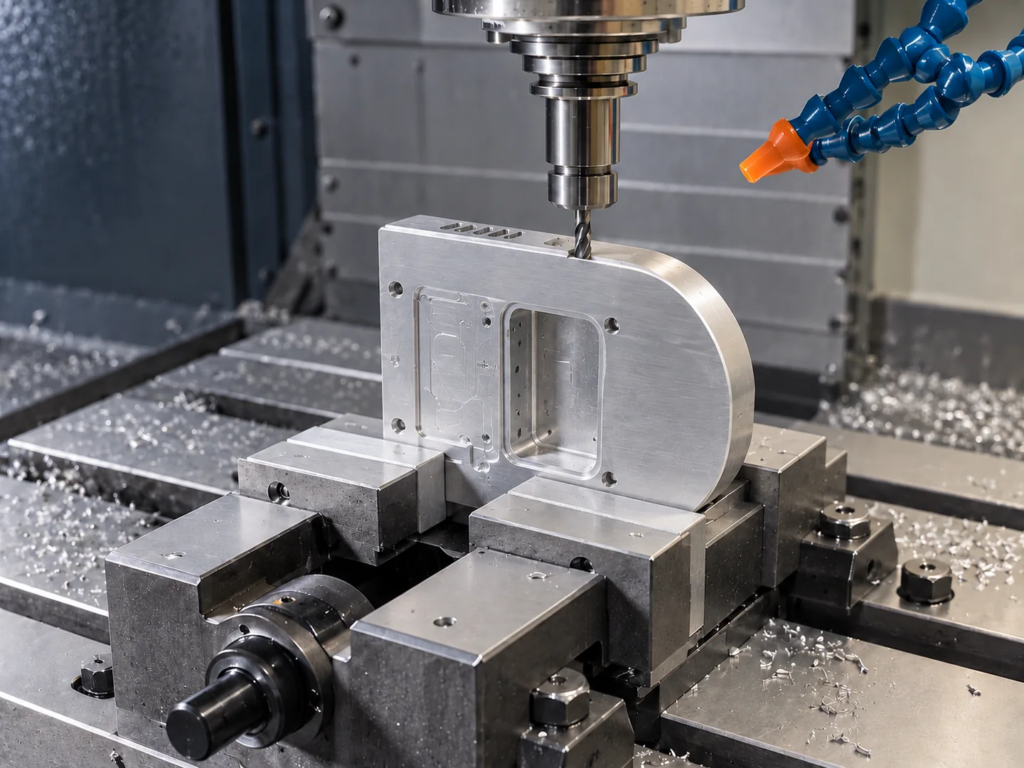
The two-stage milling study pairs an original operation record with top-face and side-face access illustrations. The setup sequence explains access; it does not itself prove a positional result.
For the teaching plate, A/B/C identify the locating faces. F2 checks the illustrated centre distance only. A real hole pattern may also require position, orientation or form controls that this sketch does not specify. Thin parts may also need an explicit free-state or restrained inspection condition.
On a circular flange, the seating face, locating bore and angular reference determine how the hole pattern is evaluated. A turned shaft or sleeve uses the same functional reasoning to connect fitted diameters, shoulders and runout to the specified datum axis.
A size result does not establish form or position
Diameter, surface form and axis location describe different characteristics. F1 can fall inside its size limits while an unexamined relationship still prevents assembly. The drawing standard and function determine which controls are needed.
A bore and shaft also work as a pair. Their clearance, transition or interference depends on both limits, with material, temperature and final treatment taken into account. A controlled mating-interface drawing helps keep separately supplied components consistent.
General tolerances are useful where they suit the function. Local exceptions carry the requirements that need them. Conflicting defaults or an ambiguous general note need resolution before release.
Give surface texture its own requirement
A correct shaft diameter can still have an unsuitable working texture. A polished-looking face may still fail a form requirement. The surface’s function determines which characteristics belong on the drawing.
A roughness callout needs a parameter, units and limit on the intended face. Ra is the arithmetic mean of absolute profile deviations from the mean line. Rz describes profile height under the specified standard; older and newer conventions can differ. There is no universal conversion multiplier suitable for acceptance.
Include the measurement conditions that change the result
Mitutoyo’s surface-roughness guide covers profile parameters, filtering, sampling/evaluation lengths and measurement conditions under the standard editions it cites. The applicable drawing standard and revision govern the part. Direction and available stylus access also matter on a small land or interrupted face.
Texture limits need a measurement stage when treatment follows machining. The material and finish guide follows preparation and treatment. Appearance limits for colour, gloss or permitted marks remain separate. A low roughness limit on every surface can add work without clarifying how a clearance face functions.
Add the local detail a model can leave unclear
Thread system, size and class belong with the usable thread depth. Drill depth is a different value. An insert needs its own requirement and acceptance condition.
Blind or intersecting holes may need controls that an external view cannot show. A fluid passage and a fastener hole can have different requirements at the intersection, including burr removal and verification.
An edge note should preserve the working geometry: a specified chamfer or radius where size matters, sharp edges where needed, and restrictions around seals or locating shoulders. Internal pocket corners need an allowed radius or relief that suits the mating part and tool access. The machining process guide connects radius, depth and support.
For a threaded fitting, the connection designation and seal geometry need to appear together. Thread gauging checks the specified thread; any leakage requirement needs its own defined test configuration and acceptance criterion.
Apply the same reasoning to other part forms
A turned part with secondary milling
The turning-then-milling study shows a cylindrical form receiving another operation. A side hole needs the correct diameter and, where function requires it, a controlled relationship to the axis, locating shoulder or orientation feature. The drawing communicates that relationship while the supplier plans the holding sequence.
A pocketed housing
In the pocketed enclosure study, the cover or sealing face, locating bore and mounting pattern need attention separately from clearance recesses and outer appearance. The final fit and positional limits must survive any finishing operation.
Choose a method that answers the callout
| Characteristic | Method question | Useful report information |
|---|---|---|
| Size or fit | Can the method check the specified limits in the final condition? | Feature number, result or functional-gauge outcome, and stage. |
| Form, orientation or location | How is the feature evaluated against the stated references? | Datum references, method and reported characteristic. |
| Surface texture | Can the instrument reach the working area with the required settings? | Parameter, units, result and measurement conditions. |
| Appearance or treatment | Which reference or test establishes the requirement? | Appearance approval or process-specific verification. |
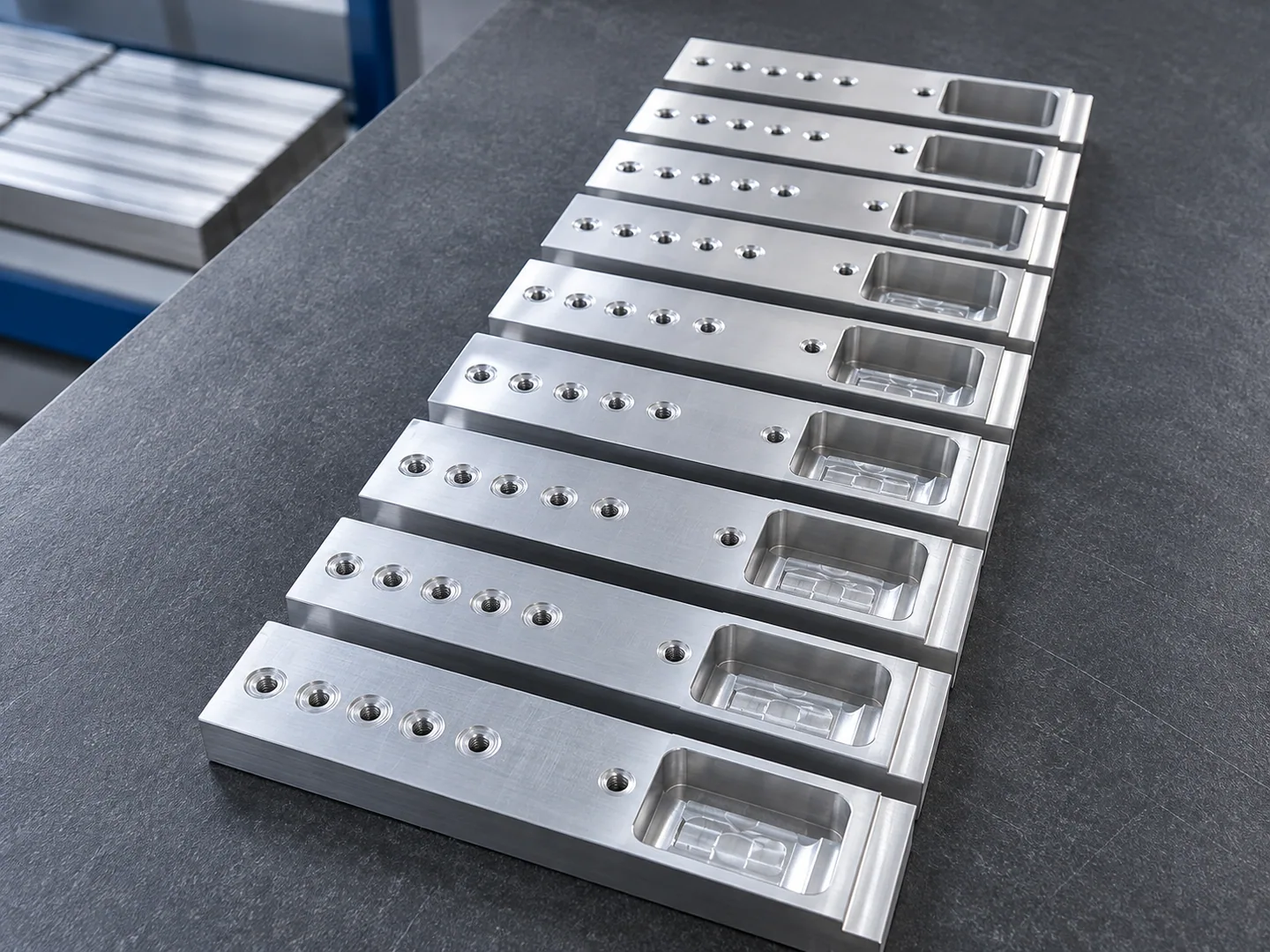
A CMM can suit some feature relationships; a bore-size check or texture measurement answers a different question. Access, range, measurement uncertainty and the required evidence affect the method. First-article, batch sampling and checks on every part should be specified separately, together with any calibration, traceability or test records.
In the illustrative inspection sheet, F3 reads 12.08 mm against 11.95 to 12.05 mm. That failed thickness check holds release even though F1 and F2 pass their numerical comparisons. The teaching sheet does not demonstrate a complete inspection or an instrument’s suitability. Inspection methods and required records are agreed for the actual order.
State when and how the part is measured
A limit needs a measurement stage. Coated or masked areas and operations that alter a working face affect whether acceptance belongs before treatment, after treatment or at both stages. The teaching plate uses the final machined condition with no treatment allowance.
A flexible part measured free can differ from the same part held against a fixture. Plastics and temperature-sensitive fits may also need material and environmental conditions with the requirement.
Sample approval covers the configuration and checks recorded. An uncoated sample cannot establish the finished coating’s fit or appearance. The sample approval checklist keeps that scope and any open items with the release decision.
Identify the stage of each reported result
A locating bore may have an in-process machining result and a final result after treatment. Use the same feature reference, with the stage recorded on each row, so receiving inspection can identify the accepted condition. A passing earlier measurement cannot establish the size of a subsequently altered surface.
The EX-MOUNT-01 exercise uses a final machined condition before surface treatment. A production drawing that requires a coated or masked fit needs its own completed-state limits and checking plan. For feature-level boundaries, use the anodizing masking guide with the released drawing.
Release one consistent drawing package
- Files
- Part number, units and revision match across the model and drawing. A named governing document or controlled model-based dataset resolves authority.
- Material and surface
- Grade, condition, finish, masks and the applicable acceptance stage. Required material and treatment records belong here too.
- Project requirements
- Applicable standards and revisions, traceability, end use and export requirements.
- Inspection scope
- Dimensional, appearance and functional checks, with frequency, methods and available report format settled before machining.
A revision should identify the changed features and their effect on price, machining, sample approval and repeat production. Conflicting notes need a corrected controlled package; an accepted deviation needs its own linked approval record.
Questions before sending the files
Can I start with a STEP file?
Yes, it is useful for discussing geometry. The quotation and inspection still need any material, tolerance, finish and acceptance information missing from the model. A model-based project needs an identifiable controlled requirements dataset.
Can the supplier propose a different datum scheme?
The supplier can raise access or measurement concerns and propose a change. The responsible designer decides whether it suits the assembly, then approves the revised requirement before production.
Does an approved sample release every later batch?
No. Approval covers the sample configuration and checks recorded. Later batches still follow the released revision, material, finish and inspection requirements. A change or an unresolved condition can require further approval.