
Choose the CNC machining route
The working surfaces of a part determine where a cutter needs to reach and how the part can be held. Turning, milling and multi-axis work address different shapes and access problems; one part may need a combination.
On this page
Choose by geometry
A shared axis, pocket, mounting face or off-axis hole suggests an operation. Their relationships determine the sequence, with the complete model, drawing and quantity needed to choose a workable route.
| Route | Start with the geometry | Define for review |
|---|---|---|
| CNC turning | Shafts, sleeves, discs and fittings. | Datum axis, diameters, shoulders, threads and runout; identify secondary milled features. |
| CNC milling | Pockets, slots, contours and mounting faces. | Datums, pocket depths, hole positions, stock and clamping surfaces. |
| Multi-axis machining | Angled faces and features approached from several directions. | Common datums, angular relationships, tool access and fixture clearance. |
A part may need more than one process. Indexed positioning and simultaneous multi-axis motion are different operations; the route must suit the drawing. It also needs a practical way to hold the part and inspect the finished features.
CNC turning or milling: read the whole part
Start with an axis for rotational features
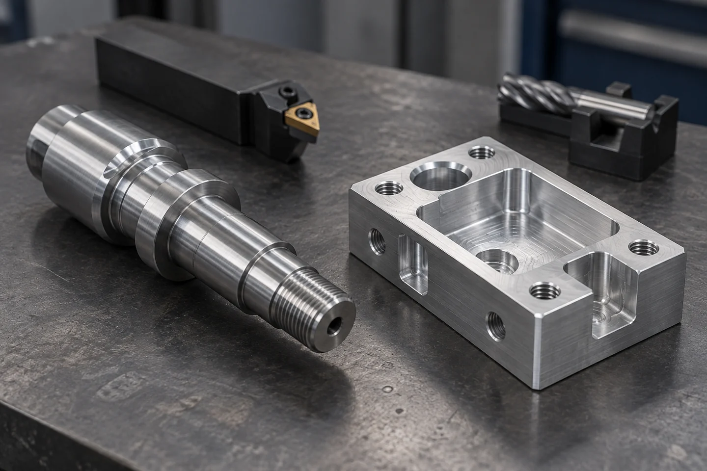
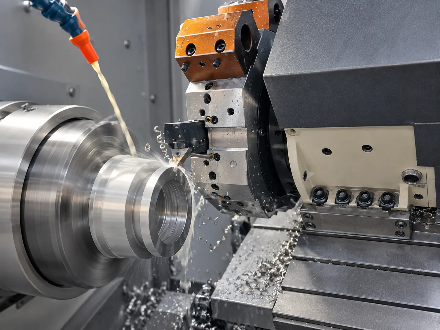
Turning is a useful starting point for diameters, bores, shoulders and other features arranged around an axis. A stepped shaft, sleeve or flange can have several such features even when its final outside outline is not entirely round.
A flat, slot or off-axis mounting feature may need milling after turning. Its angular orientation and position relative to the turned surfaces must be defined so the machining route preserves the relationship needed in assembly.
Start with faces for pockets and prismatic forms
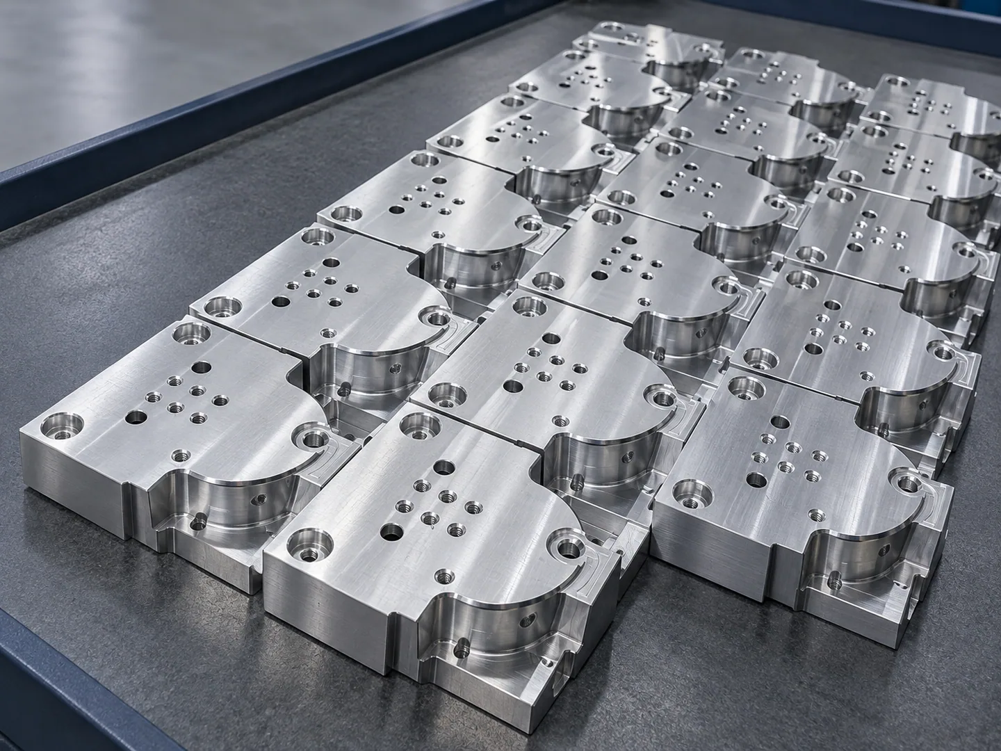
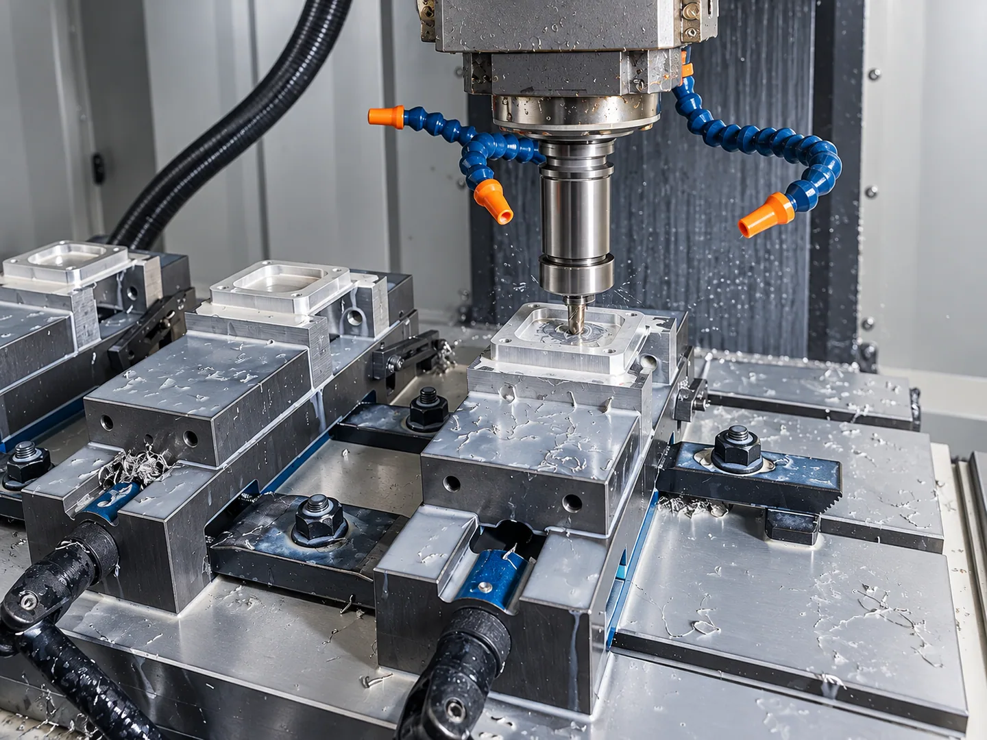
A housing or block can need mounting faces, recesses and a pattern of holes. Milling provides access to those features from suitable cutting directions. A circular pocket in a block does not, by itself, make turning the preferred route.
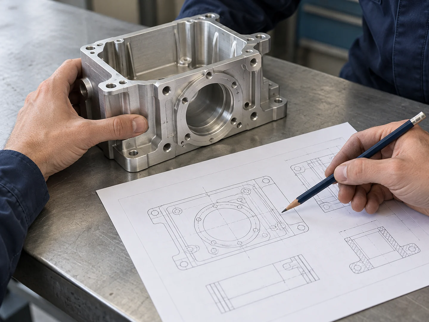
Compare the prismatic-part study with the pocketed enclosure study. In each, the surrounding faces and remaining material help explain how the part can be held and which features need a common reference.
For a part that needs both processes, check which features can locate later operations and which surfaces remain accessible. Finishing and the acceptance condition also affect the choice between separate setups and a combined machine.
Choosing between three-axis, 3+2 and simultaneous five-axis
The decision starts with the cutting directions required by the model. Features accessible from fixed orientations may suit three-axis work with suitable repositioning. Angled access can make indexed positioning useful. A surface requiring the tool orientation to change during a cut calls for a different review.
In indexed 3+2 work, the rotary axes orient the workpiece for cutting at a selected position. Simultaneous five-axis machining coordinates linear and rotary movement as the cut requires. Rapid Axis explains this distinction; it does not mean every feature on a five-axis machine needs simultaneous motion.
| Approach | When to discuss it | What still needs review |
|---|---|---|
| Three-axis with separate setups | Features can be reached from practical fixed holding orientations. | How each setup locates the part and preserves the required relationships. |
| Indexed 3+2 positioning | Different fixed tool directions help reach angled or multi-face features. | Rotary and fixture clearance, tool access and any faces hidden by the holding arrangement. |
| Simultaneous five-axis | The cutting strategy needs coordinated changes in tool orientation. | The complete surface, toolpath, holding, clearance and inspection requirements. |
More accessible faces can change the route
Grouping features into fewer manual holding operations can be useful when their positions depend on one another. It can also change preparation, tooling and the space available around the part. Compare those effects against a conventional sequence at the quantity you actually need.
Compare the complete route against the required tolerance and quantity. The CNC cost guide separates shared preparation from the work repeated on each part.
For an impeller model, the blade passages and roots make this distinction concrete. The cutter and holder need a collision-free approach along the required surfaces, with the hub and fixture included in the route review.
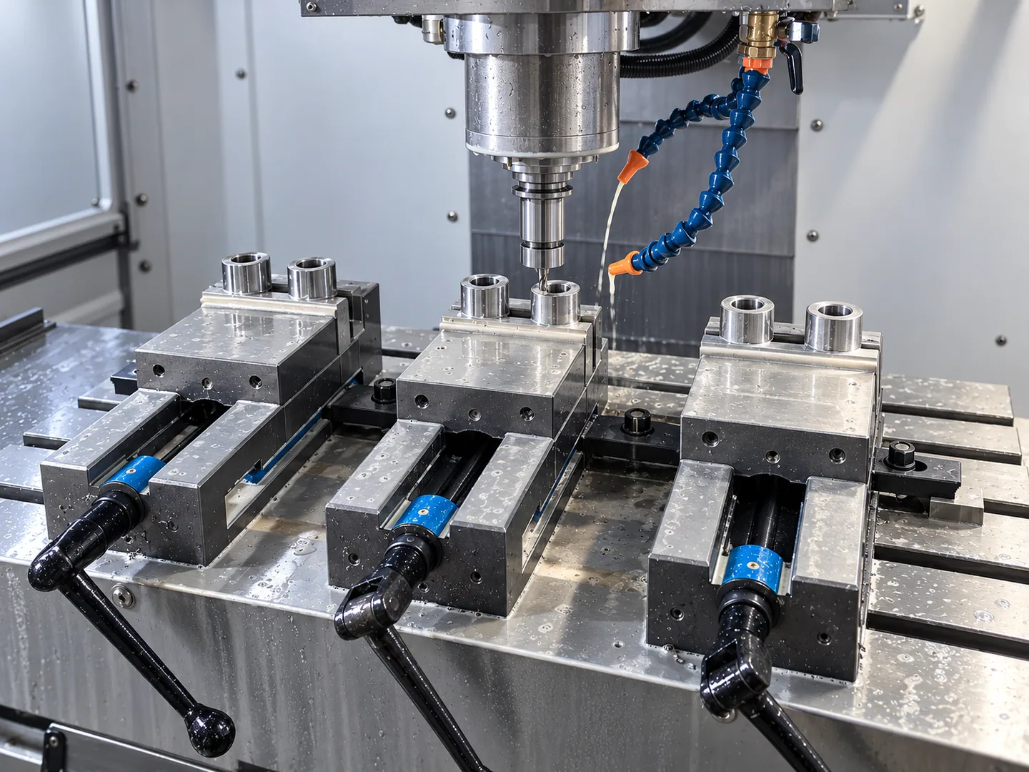
Two milling setups: keep the features connected
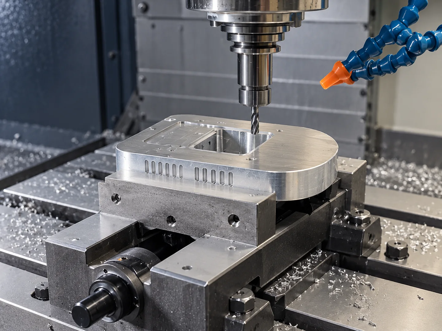
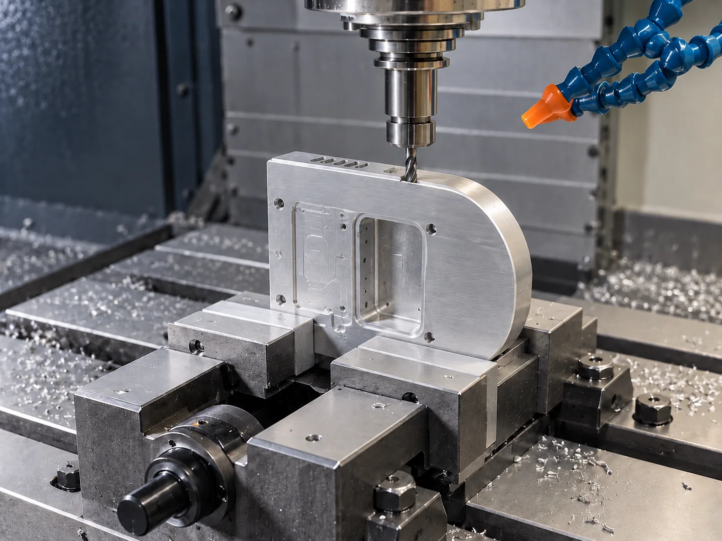
The two-stage milling study records two operations on one component. For a new part that needs repositioning, the machining plan must keep newly cut features related to the same drawing datums.
Follow the locating surfaces into the second setup
If a side feature is located from an already machined face, the second setup needs suitable locating surfaces and access to the next face. The drawing defines the required relationship and its limits.
There may also be surfaces that can be completed independently. Separating those from the features that share a close relationship helps explain where the process and inspection effort should go.
A second setup can be a sensible choice
A straightforward reorientation may suit the part and order quantity. Review the locating method, support and inspection before deciding it needs a different machine strategy. If a later design change moves a hole to another face, revisit the route because the earlier access and holding assumptions may no longer apply.
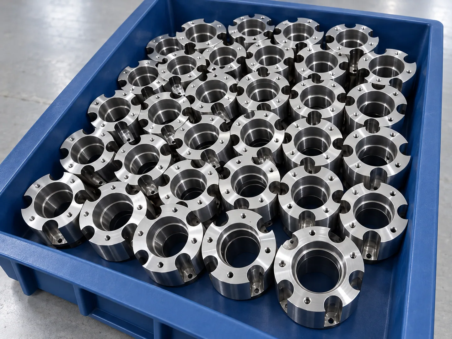
A turned body with milled features
The turning followed by milling study connects a cylindrical form with a secondary milling setup. It is a useful example when the round body alone does not describe the finished component.
Define the features from the axis and locating face
A flange may need its mounting pattern positioned relative to a bore. A shaft may need a flat clocked to another feature. In both cases, separate dimensions for the turned and milled features are only part of the specification; their relationship must also be defined.
Include the relevant axis, locating face, orientation and acceptance limits. The responsible design engineer sets that datum scheme. The machining review then considers how to locate the part for the secondary work and how to verify the relationship afterwards.
For a comparable quotation, include the turned geometry and secondary features under the same revision, final condition and inspection scope.
Multi-face parts: review access around the fixture
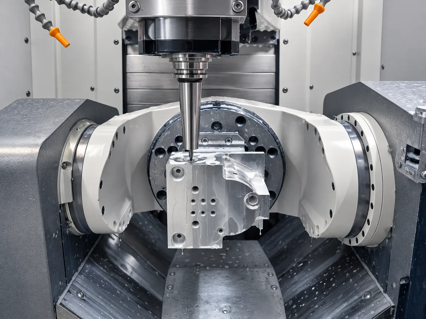
The multi-face machining study shows a workpiece around a rotary setup. Use it to discuss features approached from different directions and the space needed to reach them.
The cutter is only one part of the clearance question. Its holder, the spindle approach, the fixture and the rotating workpiece all have to fit within the proposed operation. A feature can be visible in a model and still be obstructed in a particular holding arrangement.
Separate angled features from continuously changing surfaces
A group of holes on fixed angled faces raises an indexed-positioning question. A contoured surface can raise a tool-orientation question during cutting. Both deserve a complete model review, but they do not automatically imply the same operation.
Rotary workholding gives access to features on several faces. The drawing and route review determine whether simultaneous motion is needed, along with the required acceptance checks.
Tool access, deep pockets and thin walls
Check tool reach, corner radii and support in each orientation
A tool must reach the surface with space to cut. Pocket depth, internal corners, nearby walls and holder clearance can restrict that access. Rotating a component can help with an approach direction, while the cutter shape and remaining material still need consideration.
Where access is restricted, a permitted radius or local relief may be worth reviewing with the design engineer. Sandvik Coromant’s closed-pocket guidance illustrates how pocket angles and tool choice interact. Review the actual depth, radius and tool clearance against the controlled model.
Pockets, thin walls and clamping surfaces
In the pocketed enclosure study, a recess leaves walls and interfaces around it. For a new design, identify pocket depth, corner requirements and the surfaces that locate or seal against another component.
The route needs support for the material left behind as well as access for material removal. Mark whether dimensions apply in a free or specified restrained condition when that distinction matters, and agree the inspection method.
Blind holes, threads and internal features also need a defined access direction and depth. Show the geometry clearly and identify what can be changed. A complete section or model view often resolves an ambiguity that a single outside view leaves open.
Starting from a cast housing also brings the blank into the route decision. Stock must remain at the finished features after the first locating arrangement is established. A convenient tool direction cannot compensate for missing stock or a conflicting bore-to-flange relationship.
Tolerances, final finish and inspection
Feature tolerances and datums belong on the drawing. Achievable limits depend on geometry, material, setup, finish and measurement method, which an axis count alone cannot establish.
Cross-setup dimensions connect operations. On a turned-and-milled part these may relate to the axis; on a multi-face part they may connect faces through common references.
Keep the treatment and measurement stage in the same discussion
A coated or masked interface needs its final acceptance state defined. State which surfaces receive treatment and whether the size, fit and surface requirements apply before or after it. The material and finish guide covers that specification.
Agree the checks, measurement methods and required records for your quantity. The critical drawing features guide helps connect each requirement to a measurable feature.
Quantity can change the preferred route
A prototype can justify a simple flexible holding arrangement, while a repeat batch may justify different preparation. Include both the immediate quantity and a separately identified repeat expectation. If the route changes between sample and batch, review its effect on the approved features and inspection plan.
Compare two proposed routes against the same features
If one supplier proposes separate turning and milling while another proposes a combined machine, ask how each route locates the secondary features from the required axis and face. Compare the protected contacts, final treatment and stated checks at your order quantity. The machine description alone cannot establish which offer includes the required work.
For a contoured impeller, the same review also needs the complete cutter-and-holder approach between the blades. The impeller model guide connects those surfaces to the route and inspection review. Keep any proposal to alter a controlled surface separate from approval of the original geometry.
Turning, milling and multi-axis setups
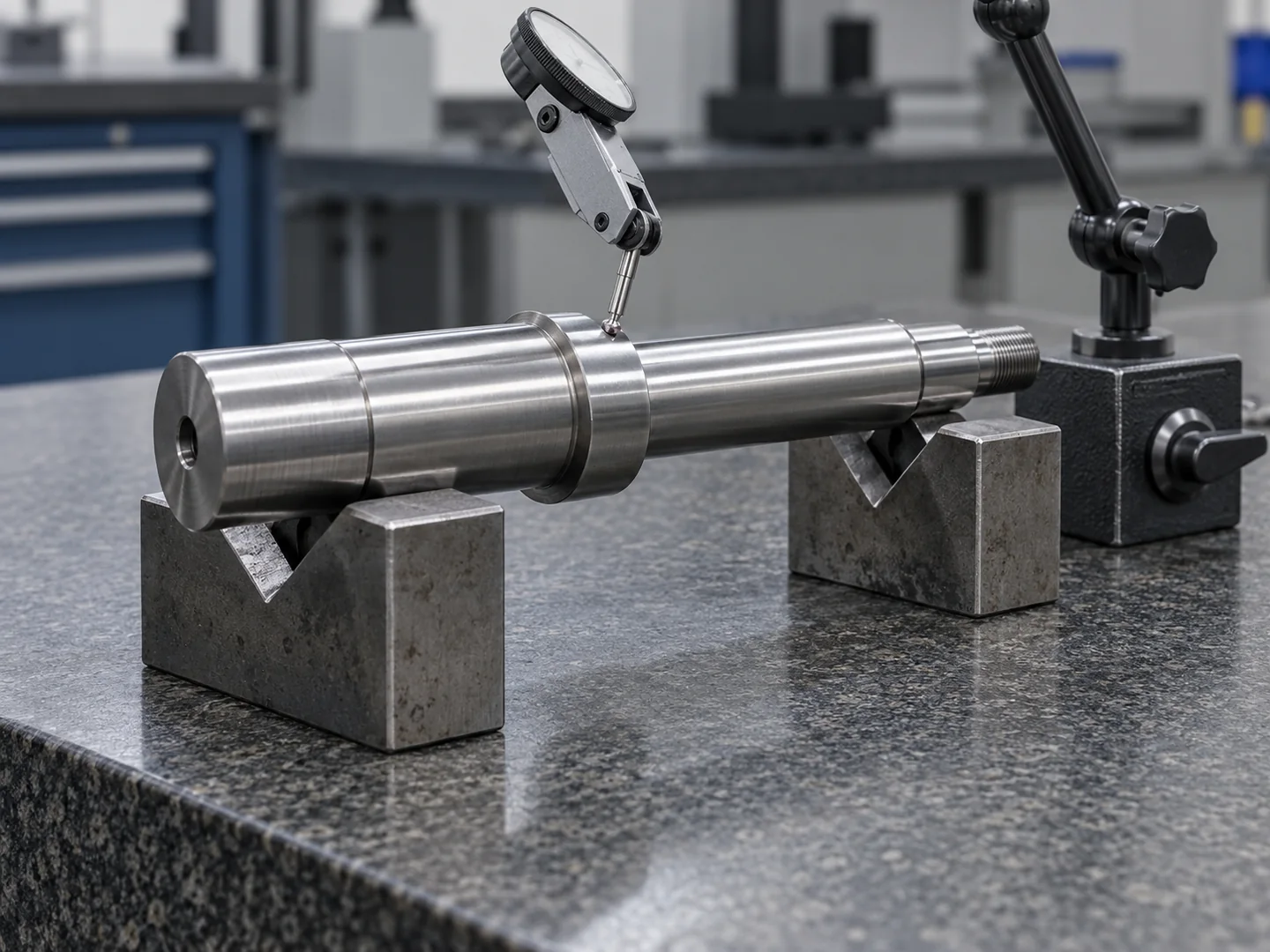
Compare cutting directions and workholding in the turning, milling and multi-axis setups below. Use the detailed studies above to relate access and locating surfaces to your drawing.
The complete model and drawing need part and stock dimensions, material and weight. Working space, fixture clearance, support and feature relationships then determine whether the proposed route can meet the acceptance limits.
Questions about choosing a CNC process
Can five-axis machining remove every second setup?
No. The holding arrangement still covers or constrains part of the component. Some surfaces may require another holding orientation, and the complete part must be inspected in the agreed final condition.
Can five-axis machining make a perfectly square internal corner?
Changing orientation does not remove the radius left by an ordinary round end mill at that corner. Explain the mating requirement and discuss a permitted relief, a radius change or another separately reviewed process.
Do I have to choose the machine before requesting a quote?
You can describe the required part and ask LZZ to review the route. Send the complete model, drawing revision, material, final finish, quantity and critical features. Identify any process explicitly required by your specification.
How do I compare a combined route with separate turning and milling?
Compare the complete work, including how secondary features are located and checked. Include preparation, final finish, inspection records and quantity. A machine description alone does not show that two quotes cover equivalent scope.