
What Matters When Ordering a Custom Indexing Plunger
An indexing plunger must enter the mating hole, engage far enough and retract as required by the mechanism. Its drawing needs the pin and mounting geometry together with the required travel and operating behavior. Define whether the order covers individual machined parts or a complete assembly, then agree separate dimensional and functional checks.
On this page
Begin with the mating hole and installed position
The pin diameter is only one part of the fit. The mating hole, alignment and installed position determine whether the pin can enter and engage as intended. A well-sized pin can still bind if the mounted body points it away from the hole or the support changes under use.
Provide the mating hole definition and the assembly position of the body. Identify the required engagement, available space and any change in alignment during operation. If the plunger locates a movable member, the design review needs the conditions in which that member will be aligned for engagement.
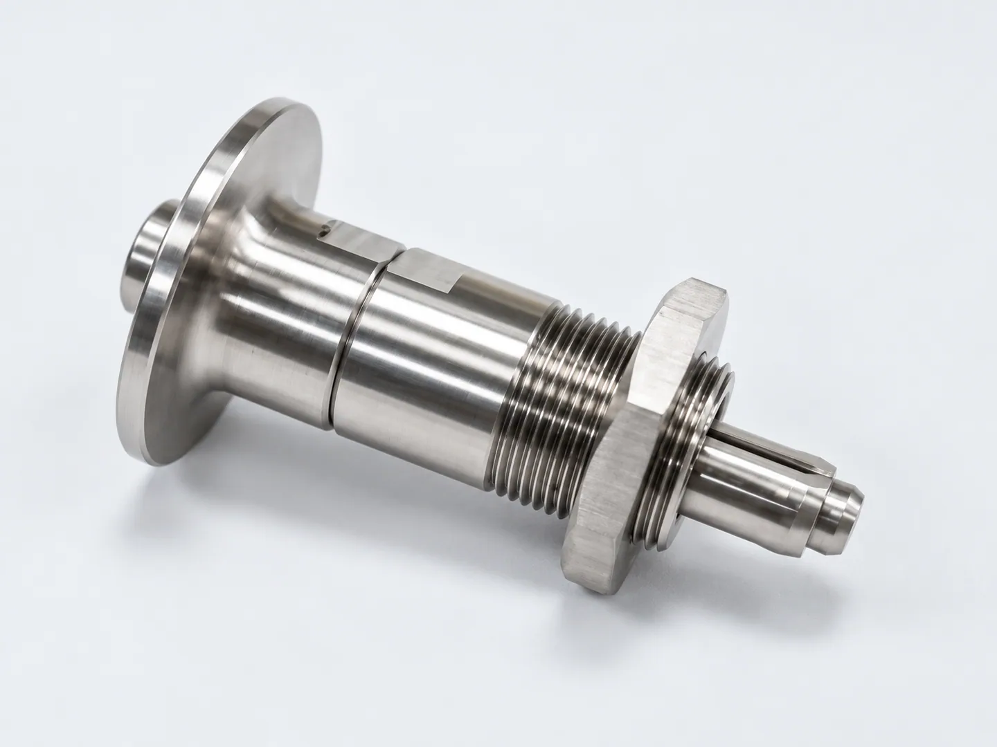
The indexing-plunger reference combines a projecting pin with a mounted body. Pin alignment controls entry into the mating hole; the body’s installed position controls how far it reaches. Required load capacity and operating life belong in the application specification.
Choose the clearance and geometric controls from the mechanism’s function. A close locating fit can conflict with easy engagement where alignment varies. The responsible designer should resolve that tradeoff with the mating arrangement, while the machining supplier reviews how the controlled parts can be made and checked.
Define the movement the mechanism actually needs
Check the movement with the body in its intended mounting position. The pin must reach the mating feature and withdraw clear of it, while the handle and retaining hardware remain accessible. Installed depth affects all of these clearances.
State the required normal position and the behavior during operation. Some designs return automatically when released; others include a rest position that holds the pin retracted. An additional lock or retention function is a separate design feature and should be described explicitly.
Ganter’s GN 413 product information distinguishes designs with a rest position that holds the pin temporarily retracted. Specify whether the custom mechanism needs that behavior. The GN 413 dimensions and ratings apply to that standard product and cannot establish the requirements for the LZZ reference.
For a custom mechanism, describe the required movement in the installed configuration. Include the space needed by the handle, knob or actuator and any surrounding obstruction. A loose assembly tested on a bench may not demonstrate the clearances available after installation.
Any unresolved latching or rest-position choice should be identified during the inquiry so the component design and quote use the intended mechanism.
- A · Pin fit, projection and required movement
- B · Spring behavior in the specified working range
- C · Body mounting and installed position
Connect each requirement to its own acceptance check
| Requirement | What needs definition | Acceptance question |
|---|---|---|
| Pin and mating fit | Pin diameter, working length, mating hole and alignment. | Which size and geometric checks represent the required engagement? |
| Body mounting | Thread, locating face, adjustment and installed depth. | How is the installed position controlled and retained? |
| Projection and travel | Required extension, usable retraction and clearance. | Is travel checked in the specified installed configuration? |
| Spring behavior | Required force or return behavior over the working range. | Which positions, conditions and method define the functional check? |
| Operating life or load | The application requirement and supplied configuration. | What separate test or design verification is required and who performs it? |
The drawing covers the machined features; the functional acceptance instruction covers the assembled movement. Keep both attached to the same component revisions so a change to the pin, body or purchased spring can be reviewed against the installed mechanism.
Pin projection, retraction stroke and engagement depth
Projection is the distance the pin extends from the defined body reference in a stated position. Retraction stroke is the movement available to withdraw it. Engagement is the length actually entering the mating feature after the body is installed. These dimensions are related, but the mounting arrangement determines how they combine.
Consider a plunger mounted beside a moving plate. A gap between the body and plate consumes part of the projected pin length before the pin reaches the hole. Screwing the body farther into its mount changes the reach, while the retaining nut and operating handle still need usable clearance.
At the withdrawn position, the pin needs to clear the moving feature by the amount required by the mechanism. A test of total travel on a loose plunger may miss interference from the installed handle, surrounding structure or mounting hardware. The functional check should use the specified installed position.
A spring-force value needs a stated working position: initial movement and a later compression are different points in the stroke. For an engagement or withdrawal check, record the configuration, measurement direction and permitted result with the functional acceptance record.
The return force also differs from the load capacity of the installed mechanism. That capacity depends on the engaged pin, body, support and engagement geometry. If it is part of the order, specify the separate evaluation and who is responsible for it.
Show the pin's working engagement in section
Where the pin has a permitted lead-in, show it separately from the working length required to enter the mating hole. A nose that starts to enter does not establish that the mechanism has reached its specified engaged position. The assembly view should show the installed gap, pin position and mating-hole region used to assess that requirement.
Use the same mounted configuration for the agreed withdrawal and return checks. If the first assembly needs adjustment to the body depth or retaining hardware, record the accepted position and revise the controlled setup information before the batch is released. This gives later inspection a reproducible configuration, rather than an instruction to adjust each unit until it seems to work.
Material, sliding surfaces and component supply
The pin and body may have different material or surface requirements. Specify the grade, condition and any treatment for each controlled component. Where wear, corrosion exposure or another service condition matters, include the relevant requirement so material selection and acceptance can be reviewed together.
A finish that suits the outside of the body may be unsuitable for a close sliding interface. Define the final surface state of the pin and guide surfaces, with any applicable edge or appearance requirements. The mechanism needs to move in the accepted final condition, after the complete treatment and assembly route.
Clarify whether springs, handles, retaining components or mounting hardware are included. A machining quotation for a body and pin is different from a quotation for a complete functional assembly. The component list and assembly definition should make that distinction visible before the order is released.
For repeat production, keep the approved component revisions and any selected purchased-item specifications together. A change to a spring, surface treatment or retaining feature can affect the operating behavior even if the outer dimensions remain unchanged.
Our CNC turning service reviews the machined features and proposed supply scope. The quotation needs to identify which assembly, force, load or cycle checks are included, with the relevant procedure and acceptance criteria.
Prepare a release that machining and assembly can both use
A complete package connects the individual part drawings to the required installed behavior. It should allow the supplier to quote the actual work and give receiving inspection a practical basis for acceptance. If an existing standard product is being replaced, confirm the approved functional definition instead of relying only on measured outside dimensions.
- Pin, body and any other controlled component drawings, part numbers and revisions.
- Mating-hole information, installed position and required engagement.
- Mounting thread, locating faces, usable travel and operating clearances.
- Material and final surface requirements for each working component.
- Included springs, handles or retaining hardware and the controlled assembly definition.
- Dimensional checks, return or force checks and any separate load or life-test requirements.
- First-assembly approval, batch quantity, sampling and required records.
For the first assembly, record the mounted configuration, checks performed and revision accepted for the next batch in the sample approval record. Keep exceptions and unresolved application tests visible alongside the completed dimensional results.