
What to Check Before Machining a Cast Housing
Before a cast housing reaches machining, establish what the blank contains, where material must remain and which surfaces will locate the finished features. A usable outside envelope is only the start. Machining stock, core position, retained cast walls and inspection access all need to suit the finished drawing.
On this page
Distinguish the casting drawing from the finished drawing
A casting drawing describes a supplied blank. A machining drawing describes the component that must fit into the assembly. The two documents need compatible revisions, but they do different jobs. A casting dimension does not automatically establish a finished bearing fit, sealing face or mounting-hole position.
Mark every surface that will be machined and identify the surfaces that remain as cast. Retained surfaces can affect clearance, wall thickness and the first locating arrangement. If the model shows only the finished geometry, the machining supplier also needs the blank geometry or a sufficiently detailed incoming inspection plan.
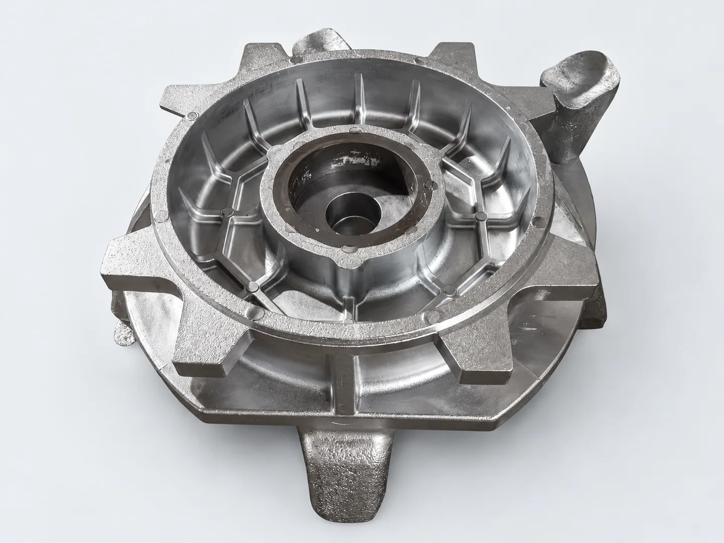
The ribbed cast housing combines a central bore with surrounding walls and mounting features. Finishing the bore requires enough stock around its full circumference while preserving the specified wall. The blank drawing needs the casting process, alloy and condition as well as the outside envelope.
The Steel Founders’ Society of America’s ordering guidance calls for drawings that identify machined surfaces and locating datums on steel castings. Its allowance guidance is specific to steel; the foundry and machining supplier must establish suitable allowances for an aluminum or other casting process.
- A · Retained cast envelope
- B · Stock on a surface to be machined
- C · Finished bore and its datum relationship
Incoming casting checks: machining allowance and retained walls
Incoming checks should establish whether the supplied blank can produce the required part. Look beyond the outside dimensions. A core shift or local wall variation can leave too little material around a bore even when the general envelope appears generous. The review needs the relationship between internal and external surfaces.
| Incoming item | Question to resolve | Record to retain |
|---|---|---|
| Identity and condition | Does the material, heat treatment and revision match the order? | Blank identification and the specified material or treatment records. |
| Machining stock | Is stock available at every finished feature after the blank is located? | Agreed stock checks, including internal or offset features. |
| Locating surfaces | Are the proposed contacts stable and repeatable? | Datum targets, contact restrictions and any first-operation preparation. |
| Retained walls | Will the required wall remain after machining? | Sections or agreed wall checks tied to the finished geometry. |
| Defects and repairs | Which indications, repairs or exposed conditions require a hold? | Applicable criteria, disposition authority and any specified examination. |
Do not leave the acceptance of exposed porosity or a repaired area to an informal decision at the machine. The purchasing specification should identify the applicable criteria and who can approve a deviation. If a particular pressure boundary or stressed region needs an additional examination, define it with the responsible engineer and the casting supplier.
A sample blank can help validate the proposed checks, especially where the machining datum is created from a rough surface. Keep the sample layout and any agreed changes with the controlled documents so later deliveries are assessed on the same basis.
Decide whether the blank can proceed before cutting
| Incoming finding | Decision to resolve | Record to retain |
|---|---|---|
| Stock is present at the finished features in the proposed locating arrangement. | Proceed under the agreed incoming and first-part inspection plan. | Blank identity, revision and the stock-check results required by that plan. |
| A bore or wall cannot reach the released geometry from the required datums. | Hold for an approved disposition; shifting a controlled bore is a design change. | The affected feature, layout result and authorized drawing change or rejection. |
| A repair, exposed porosity or another specified condition needs approval. | Apply the purchasing criteria and approval responsibility before further work. | The finding and the accepted disposition linked to the casting or batch. |
When the customer supplies the blanks, the quotation should identify who checks incoming stock and what happens to an unusable blank. If the machining supplier also arranges the casting, the blank and finished-part requirements still need a common revision basis. A price for cutting alone leaves the foundry coordination and rejected-blank responsibility unresolved.
Core shift and loss of machining allowance
Machining allowance is material intentionally left for later cutting. It must be present where the finished surface will lie after the blank has been located. An allowance stated on one face does not prove that stock remains around every internal bore or on the opposite wall.
Consider a cast housing whose internal opening is displaced toward one side. The outside can still look centered and have generous stock. Once the finished bore is positioned from the required mounting datums, one side may clean up while the other reaches a thin wall or fails to clean up at all.
Moving the machining axis toward the cast opening can preserve more wall, but it also moves the finished bore relative to the flange and mounting pattern. That is a design change when those relationships are controlled. An incoming stock check should evaluate the blank in the proposed locating arrangement before the first cut commits the part.
The incoming review should record whether the blank is suitable, needs an approved disposition or cannot produce the released geometry. If more allowance is proposed for a future delivery, the foundry also needs to review the casting process and wall geometry against the finished-part drawing.
Transferring datums from cast surfaces to machined features
The first operation often begins from cast surfaces or datum targets that will not remain as the final references. Its purpose includes creating a stable face or bore from which later operations can be located. The supplier must check that this transfer preserves stock where the remaining features need it.
A convenient flat-looking patch may be unsuitable as the only contact if its position varies between blanks. Several contacts can establish the first setup, but their locations need to be clear and accessible. Clamping should support the housing without forcing a flexible wall into a shape that disappears when the fixture is released.
For a housing containing several related bores, the finished datum scheme should follow the assembly function. The machining route can use temporary locating features to achieve it. Confusing those temporary contacts with the drawing datums makes it harder to compare in-process measurements with the final report.
The relationship between a flange and an internal bore deserves particular attention. Machining each surface to size in separate setups does not, by itself, establish their required position or orientation. Define the relationship, then agree a route and measuring arrangement that can verify it after all relevant operations.
Our casting machining review considers the blank and finished geometry together. Include known contact restrictions, lifting or handling limitations and surfaces where clamping marks are unacceptable. These details affect the fixture plan even when they do not appear in the nominal finished solid.
Connect each critical interface to a practical check
A pump body, transmission housing or structural enclosure can have very different acceptance needs. Identify the features that locate a bearing, seat a seal, connect another component or close an internal passage. Each needs the relevant size, position, surface and final-condition requirements.
Inspection access is part of that discussion. Deep internal steps or a bore behind a narrow opening may require a different measurement arrangement from an exposed flange. If an inspection feature will become inaccessible after an insert or another component is fitted, define the necessary earlier check and the subsequent assembly acceptance.
Separate dimensional checks from tests of the material or fluid boundary. A bore report does not establish leak performance, and a leak test does not report the position of every mounting hole. State the test medium, conditions, acceptance limits and records where such testing forms part of the supply scope.
Agree when deburring, cleaning and any coating occur in the sequence. Intersecting holes can leave edges inside a passage, while cleaning requirements may be more demanding than a general visual check. Define the required state and a feasible way to inspect it; do not rely on a broad note that the component must be clean.
The critical drawing features guide explains how to connect a requirement to its acceptance record. For a casting, keep the incoming blank records alongside those finished-feature checks so a later issue can be traced to the correct stage.
The information to settle before machining release
Release should follow agreement on both the incoming blank and the finished component. If the blank supplier and machining supplier work from different models, resolve that difference before a batch is committed. A note on an email is easy to lose unless it becomes part of the controlled specification.
- Blank and finished-part drawings, revisions and the relationship between their models.
- Alloy, material condition, heat treatment and the records required for the supplied blanks.
- Machining surfaces, retained cast surfaces, stock checks and minimum finished-wall requirements.
- Initial locating contacts, final datums and any protected surfaces.
- Feature-specific dimensional checks, additional examinations and separate functional tests.
- First-part approval, batch sampling, identification and the authority for repairs or deviations.
A visually similar replacement blank may have a different foundry route, geometry or treatment. Compare those changes with the locating and stock assumptions recorded at first-part approval. Keep the drawing revision and accepted exceptions with that release record.