
Which Aluminum Features Need Masking Before Anodizing?
Discuss masking wherever anodizing could affect a fitted dimension, electrical contact, sealing interface or required surface condition. The drawing should show what is treated, what remains outside that treatment and which dimensions apply after finishing. Masking is a feature-specific decision made with the selected process and mating requirements in view.
On this page
Mark the functional regions before choosing a finish note
A general anodizing note can leave important exceptions unresolved. The outside of a housing may require a consistent appearance while its locating bore needs a controlled final fit. A contact pad may need a different surface condition from the surrounding protective finish.
Begin with a feature map of the part. Identify fitted surfaces, seal interfaces, electrical contacts and any region whose dimensions or roughness are critical. Then discuss how the selected treatment will be applied and what acceptance state each region needs.
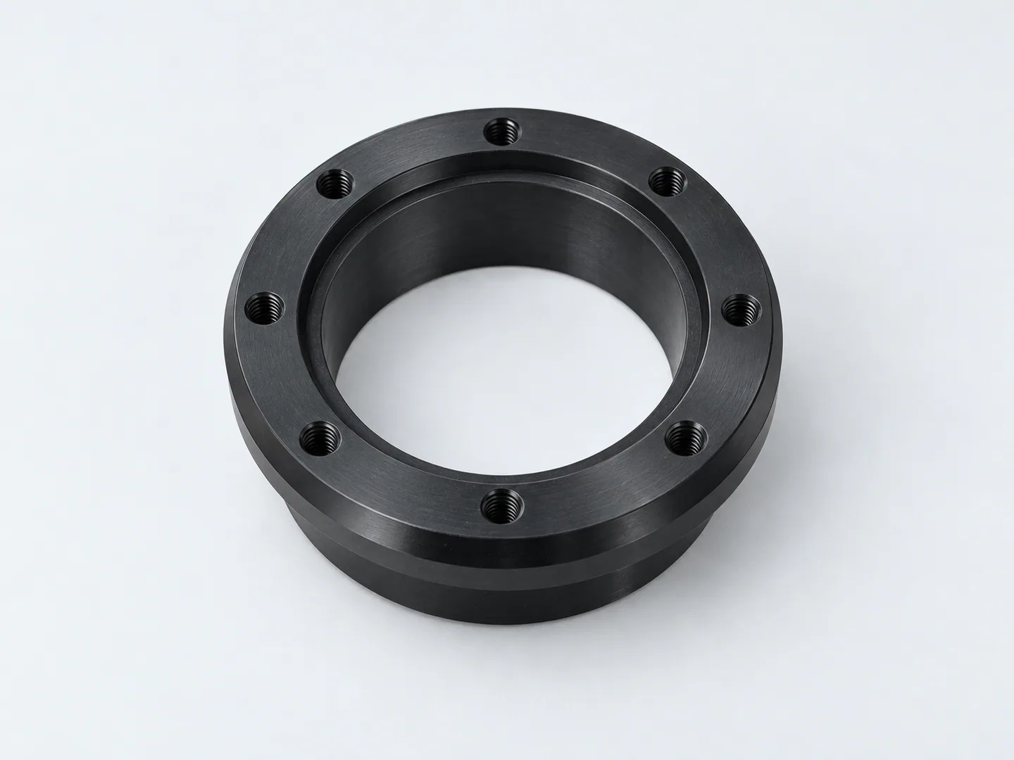
The flanged-ring reference brings a central bore, mounting faces and an exterior onto the same component. A fitted bore and a visible outside face can have different treatment requirements. The drawing needs the finish specification for each region, including any appearance reference.
Define a masking boundary on a view or section that can be understood at production scale. A note naming a bore may leave its entry chamfer, adjacent shoulder or intersecting passage unclear. Identify what happens at those transitions and who approves a proposed boundary where the drawing cannot resolve it directly.
- A · Fitted bore or controlled opening
- B · Electrical or mounting contact region
- C · Threaded or other mating interface
Control the accepted dimension after the complete process
Anodizing changes the surface condition, and its dimensional effect must be considered for the selected process. Do not use one assumed growth value for every alloy, coating type or internal feature. The machining and finishing suppliers need to agree a process that can achieve the specified final requirement.
NASA/JSC PRC-5006 discusses final dimensions, coating thickness and feature geometry within its own specified applications. The applicable process specification for your order controls the actual treatment and acceptance requirements.
| Feature | Issue to review | Drawing decision |
|---|---|---|
| Locating bore | Treatment can affect the finished fit and its surface. | Accepted final size, treatment requirement and any defined masking. |
| Internal or external thread | The final thread must meet its specified mating requirement. | Finish state, masking limits and when the thread is gauged. |
| Electrical contact pad | The required contact condition differs from the surrounding coating. | Controlled contact region and any separate surface protection. |
| Sealing face or groove | Geometry, roughness and treatment must suit the selected seal. | Final interface requirement and any boundary or edge restrictions. |
| Visible exterior | Appearance depends on the agreed material and preparation. | Controlled sample, permitted contact marks and cosmetic acceptance areas. |
If the drawing includes a machining-stage dimension as well as a final dimension, label their stages clearly. A process measurement helps control the route, while final acceptance must still use the specified completed condition.
Review masking together with the mating requirement
Masking can preserve a region from the main treatment, but it also leaves that area with a different protection and appearance condition. The design review should account for exposure, contact and any separately specified protection. An untreated region should be an intentional part of the specification.
Reaming an anodized bore or masking it before treatment
A bore that is masked before anodizing and a bore sized afterward follow different routes. Masking keeps the indicated region outside the main anodizing treatment. Reaming or another sizing operation after treatment can remove coating from the working surface, so the resulting protection and surface condition need the designer’s approval.
For example, an enclosure may need both a final locating diameter and protection around the bore entrance. A note saying only to mask the bore leaves the entry chamfer and nearby shoulder open to interpretation. A section should show the treatment boundary and the final size requirement. Any exposed region that needs separate protection should have that requirement on the same controlled specification.
Before releasing the route, have the finishing supplier review the geometry and achievable masking boundary. If the machining size differs from the final size, label both stages: the earlier measurement controls the process, while receiving inspection uses the completed condition.
Threads need a similarly specific review. Identify the thread standard and accepted final condition, including any permitted changes to the preparation or finishing sequence. The supplier should not choose an unapproved thread alteration merely to make assembly easier after treatment.
An electrical contact region needs its own specified condition and protection. If contact resistance or bonding is part of acceptance, the order also needs the relevant limits and checking responsibility. Bare appearance is only one observation about that region.
For a sealing surface, discuss the complete seal arrangement. A groove and its mating face may have different requirements, and a mask edge must not become an unreviewed change at the working interface. The finished drawing should make the selected arrangement understandable to both the processor and inspector.
Compare the available routes for a fitted bore
| Route under review | Consequence to resolve | Final acceptance information |
|---|---|---|
| Mask the indicated bore before anodizing. | That region remains outside the main treatment and may need separately specified protection. | Bore size, mask boundary and the required condition of the chamfer and shoulder. |
| Anodize, then perform an approved sizing operation. | Machining can remove coating from the working region and change its protection. | Final size, exposed region and the designer-approved surface condition. |
| Machine an allowance and accept the treated bore. | The allowance and achievable internal coverage depend on the selected process and geometry. | Process-specific preparation, final dimensional limits and required coating checks. |
Choose the route with the machining and finishing suppliers before production. A nominal coating thickness alone cannot decide between them. The mating fit, treatment coverage and protection of any exposed material must remain compatible with the assembly.
Plan for contact marks, appearance and inspection
Finishing requires a practical way to handle and contact the component. Identify surfaces on which handling or electrical contact marks would be unacceptable. Discuss permitted contact regions before production so a critical visible face is not chosen simply because it is convenient.
Color descriptions should be supported by an agreed reference when appearance matters. A named shade alone can be interpreted differently, and the chosen alloy and surface preparation influence the result. Keep visual acceptance separate from a dimensional or functional check.
Inspect the treatment boundaries as well as the treated surfaces. A final report may need the fitted diameter or thread result after processing, while a visual check confirms the location of the masking boundary. Where coating thickness is specified at particular locations, identify those locations and the required records.
Use the material and finish checklist for the grade and general treatment specification, with local exceptions on the part drawing. Machining, finishing and inspection should all work from that controlled definition.
Changes to alloy, surface preparation or processor can require a review of an earlier accepted appearance sample or dimensional route. Keep those changes visible in the approval process, particularly for fitted components repeated over several orders.
The finish information to release with the part
A marked-up model can help a discussion, but the approved treatment definition needs to be attached to the production revision. Avoid relying on colored screenshots whose meaning is not recorded. Each color or shaded region should refer to a named requirement that the supplier can check.
- Aluminum grade and condition, drawing revision and the applicable finishing specification.
- Coating type, thickness requirements where applicable, preparation and agreed appearance reference.
- Fitted bores, threads, seal regions and contact pads, with clear boundary views.
- Any separate protection required on regions outside the main treatment.
- Final dimensional acceptance, permitted contact marks and required inspection records.
- Approval responsibility for boundary changes, process changes or appearance exceptions.
For CNC aluminum parts, send these requirements with the machining drawing so the entire route can be reviewed. If a surface requirement is still unresolved, label it as an open decision. That allows the proposed machining and finishing work to be quoted against a clear scope before the final revision is released.