
Designing Aluminum Enclosures for CNC Machining
For a CNC-milled aluminum enclosure, wall thickness and pocket depth must leave room for the cutter and support for the remaining material. The lid register, board mounts and connector openings then determine which dimensions need close control. This guide covers that solid-stock machining route; an extruded body or folded sheet-metal box starts from a different construction.
On this page
Start with the surfaces that locate other parts
The cavity creates space, but the surfaces around it determine whether the assembly fits. An internal board may locate on mounting bosses. A lid may register against a rim or step. A connector may need a hole positioned from the enclosure base. Draw those relationships before tightening the tolerance of every outside surface.
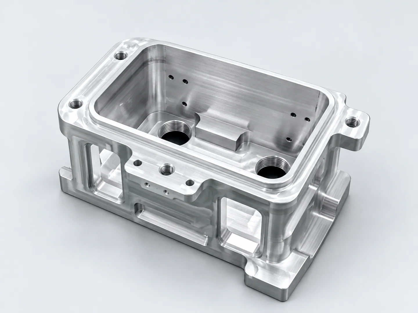
The pocketed aluminum housing has an open cavity, a closure rim and openings through the floor and sides. The drawing needs to relate those features to the mounting surfaces. Sections through the housing show how much material remains beneath a pocket and around an opening.
Give the mating lid its own part number and revision. If an O-ring, gasket or conductive contact lies between the two components, define its interface separately from the general exterior finish. A broad note saying that the housing must fit is difficult to inspect because it does not identify the controlling features.
Use a consistent set of datums for the mounting pattern and closure surfaces. The supplier can then discuss how those features will be held during machining and supported during measurement. Keep functional requirements on the drawing and allow the machining plan to develop around them.
Identify the starting form before comparing enclosure quotes
A model of the finished box can conceal how it is made. Milling a cavity from solid stock, cutting features into a supplied extrusion and assembling folded panels involve different preparation and joints. Send the proposed starting form with the model. An extrusion-based inquiry also needs the profile drawing and the definition of any separate end panels.
For the pocketed housing shown here, sections through the cavity, rim and openings are the useful manufacturing views. Compare wall support and access on those sections. A wall-thickness recommendation for a folded panel or a stock extrusion does not establish a suitable limit for this machined cavity.
- A · Closure rim and lid interface
- B · Cavity floor and internal mounting surfaces
- C · Wall sections and cutter access
Wall thickness, pocket depth and internal corner radius
A narrow, deep cavity can require a longer tool and leave little room for the holder. Making a wall thinner also reduces its support during cutting and clamping. These are related decisions: a wall that is manageable beside an open, shallow pocket may behave differently beside a deep recess.
There is no single wall thickness that suits every aluminum enclosure. Span, height, alloy, stock condition and the features left on each side all affect the review. Instead of applying a universal minimum, identify the sections that are fixed by the assembly and those that can be thickened, shortened or supported.
| Feature | Why it needs review | Useful drawing information |
|---|---|---|
| Deep cavity | Tool reach and holder clearance can restrict access. | Depth, opening size, floor geometry and permitted corner radii. |
| Tall, thin wall | Cutting or fixture loads can move the remaining section. | Wall height and thickness, support condition and critical final faces. |
| Internal corner | A round cutter leaves a radius in a conventional milled corner. | Required radius or a permitted relief based on the mating part. |
| Mounting boss | Its hole position and surrounding material must remain useful after cutting. | Hole specification, thread depth and relationship to the mounting plane. |
| Closure rim | Local changes can affect lid fit or sealing. | Mating geometry, surface requirements and the final treatment state. |
Where an inside corner does not locate a mating component, a more generous radius can give the machining plan more room. Sandvik Coromant’s inside-corner guidance explains how engagement increases as the tool enters a corner. Changes to a functional corner need the designer’s approval.
What does an R3 internal corner mean for the cutter?
As a geometric example, a 6 mm diameter end mill has a 3 mm radius. It cannot leave an internal corner smaller than R3 in a conventional milling pass. Requiring exactly R3 also gives that tool little room to turn through the corner. A smaller tool or a larger permitted component radius gives the machining plan another option. This example explains the geometry; it is not a minimum-radius rule for every enclosure.
The depth matters at the same time. A small cutter that can reach a shallow corner may need a long projection to reach the bottom of a deep pocket. That changes its stiffness and the space needed by the holder. A drawing review should consider the corner at its full depth, including any step or boss that blocks the approach.
Wall support is equally local. A short wall interrupted by mounting bosses can behave differently from an uninterrupted side of the same thickness. Where the assembly permits, leaving material around a boss or shortening an unsupported span can improve support without thickening every wall.
Price one proposed geometry change at a time
If an internal corner provides clearance, ask the designer whether its radius can increase while the lid register and mounting interfaces stay fixed. The supplier can then quote that controlled alternative. If the corner locates another component, changing it requires a check of the mating geometry before it becomes a cost option.
A useful DFM response identifies the affected feature, the proposed change and the requirement it preserves. It lets you compare the revised drawing with the original instead of accepting an unexplained instruction to make the enclosure easier to machine.
Threaded holes and tool access inside the enclosure
Holes on the bottom of a cavity need access for drilling, threading, deburring and inspection. A threaded hole close to a wall can be reachable by a small cutting tool while the holder or measuring equipment still lacks clearance. Include the surrounding geometry when asking a supplier to review a feature.
Blind threads need a defined usable thread depth and enough space for the chosen hole preparation. The final drawing should distinguish the thread requirement from the total drilled depth. Through holes require an edge condition on both sides, particularly if the exit lies on an internal surface that becomes hard to reach later.
A side port may require another holding orientation. The enclosure must remain supported without marking a finished sealing rim or crushing a thin wall. Mark surfaces that cannot be used for fixture contact, then discuss whether temporary stock or a different operation sequence is appropriate.
A section view helps compare a single deep opening with a shallow top-and-bottom arrangement. Access from opposite sides may simplify some cuts; splitting the enclosure also adds mating and fastening requirements. Review the complete assembly before choosing the construction.
Keep finishing and dimensional acceptance connected
A fitted bore needs its size specified in the final acceptance condition, even if the exterior finish is mainly cosmetic. When anodizing, coating or another treatment follows machining, identify which bores, threads and contact surfaces receive it and which remain untreated.
Separate appearance criteria from geometry. A controlled color or texture reference helps with visible surfaces; a flatness or position requirement needs an agreed measurement method. Polishing every cavity wall does not establish that a lid will sit correctly or that a mounting pattern will align.
The material and finish guide covers the grade, condition and treatment. Fitted bores, lid contacts and threads may also need feature-specific anodizing boundaries. Areas where normal tool marks are acceptable should be identified so the quotation reflects the actual requirement.
Inspection access should be reviewed before the order is released. A probe may reach a cavity floor differently from a bore gauge or height measurement. Define support and restraint when they affect the result, and agree which features appear in the first-article or batch record. Environmental sealing or ingress protection requires its own specified test and acceptance criteria.
An enclosure drawing package ready for review
A useful review package shows the complete enclosure, the parts that mate to it and the features that are still open to change. If the model and drawing contain different information, state which controls each requirement. This avoids treating an unqualified model surface as a finished tolerance.
- Current model and drawing revision, with sections through the floor, walls and recessed interfaces.
- Material grade, stock condition and required material records.
- Datums, closure fit, mounting-hole positions and any critical flatness or bore requirements.
- Internal corner limits, usable thread depths, access restrictions and protected fixture-contact surfaces.
- Surface treatment, masking, appearance reference and dimensions in the final acceptance state.
- Order quantity, requested inspection records and any separate assembly or environmental tests.
For a machined aluminum enclosure, we review the complete geometry and the stated acceptance requirements before proposing a route. A marked-up section showing where a board, lid or connector locates is often more useful than a long list of equally tight dimensions. Keep unresolved design choices visible so they can be addressed before the production revision is approved.