
Why Machined Plastic Parts Need Defined Measurement Conditions
For CNC-machined plastic parts, a tolerance needs a defined measurement state. Temperature, moisture history, support and contact force can change the comparison between a supplier and receiving inspection. Use data for the ordered polymer grade and specify the state in which its bore, shaft or mounting surface must fit; a tolerance table for an injection-molded part cannot establish those machining and inspection conditions.
On this page
Why plastic machining tolerances need a measurement state
A dimension measured immediately after cutting may not be directly comparable with a receiving result taken later in a different room. The disagreement can concern the state of the material as well as the instrument. Before adjusting a tolerance, establish how the two measurements were made.
Mitsubishi Chemical Group’s dimensional-stability guidance identifies temperature, moisture and internal stress as considerations in plastic part design and machining. Their effect varies between materials. A requirement for one grade cannot be copied to every component described simply as plastic.
For a sleeve, the bore may need to fit a shaft at assembly while the outer diameter locates in a housing. For a broad block, support can affect flatness and the position of distant features. Define whether the relevant result is free-state, supported or measured under a specified assembly restraint.
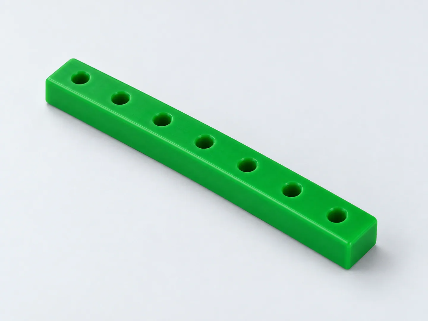
On a long form such as the perforated plastic strip, support along the length affects how the bore locations are checked. The stepped shafts and transparent components in the plastic-parts collection have different mating and handling needs. Each drawing needs its own grade and measurement state.
Name the grade before comparing tolerances
POM, PTFE and PE describe material families with different behavior. Within a family, fillers, stock form and processing history can also matter. A color or a familiar trade description is insufficient when dimensional stability, wear or an electrical property controls the application.
Specify the material designation and required stock condition on the drawing or linked material specification. If substitutions are possible, identify who can approve them and what must be rechecked. A substitute with an attractive nominal property can still change the fit, surface or behavior of a thin feature.
Ask for data relevant to the intended service environment. A room-temperature dimension and an operating clearance are related requirements, but they are not automatically identical. The design review needs the mating material, expected temperature range and any exposure that could change the polymer’s dimensions or stiffness.
Whether stress relief or annealing is appropriate depends on the stock and geometry. Agree a material-specific schedule with the supplier if either treatment is needed. Ensinger’s engineering plastics manual discusses machining heat and stress release; the current information for the ordered grade should govern the treatment.
How temperature affects a plastic bore or shaft measurement
A plastic bore and its mating shaft can both change size between inspection and operation. The clearance depends on both components in their working conditions. A room-temperature fit is therefore only one part of the design review when service temperature differs.
For an unrestrained component with approximately uniform temperature, a first estimate of linear thermal movement is ΔL ≈ α × L × ΔT. Here, L is the original dimension, ΔT is the temperature change and α is the coefficient for the ordered material over the relevant temperature range. The same α and temperature change produce a larger absolute movement over a longer dimension.
The coefficient must come from the selected grade’s data. Filled materials can have directional properties, and a restrained part may not move as a freely supported specimen does. This simple thermal estimate also leaves moisture uptake, time-dependent deformation and machining stress to be considered separately.
For receiving inspection, let the part reach the agreed condition and use the defined support before comparing results. If readings still disagree, compare measurement location and contact force as well as temperature. A thin sleeve squeezed by the gauge is a different measurement problem from uniform thermal expansion.
Clamping, gauge contact and support for plastic parts
A plastic workpiece can deflect under fixture or gauge contact. If a wall is machined while it is forced against a support, its free shape after release can differ from the shape seen in the fixture. That relationship is especially important for large open pockets and long, slender components.
| Part or feature | Condition that can affect the result | What to agree |
|---|---|---|
| Thin-walled sleeve | Clamping and gauge contact can change the apparent bore. | Support, contact method, axial measurement locations and free-state requirement. |
| Broad mounting block | A different support arrangement can change measured face relationships. | Defined support points and whether restraint is permitted. |
| Long or curved strip | Weight and handling can alter the position during inspection. | Orientation, support spacing and the feature being assessed. |
| Close fitted diameter | Temperature or conditioning differences can alter comparison. | Material-specific conditioning and measurement temperature. |
| Finished working surface | A measuring contact can mark or deform a sensitive area. | Permitted contact, appearance criteria and an appropriate checking method. |
A useful measurement plan gives the receiving team enough detail to reproduce the check. A statement that both parties used a CMM or a micrometer is incomplete if they used different support, contact or conditioning. Record the relevant setup as well as the instrument type.
Do not make every dimension tighter to compensate for an undefined setup. Identify which dimensions control the assembly, then choose a practical combination of tolerance, material state and measurement method for those features.
- A · Agreed measurement temperature and conditioning
- B · Support that does not distort the measured feature
- C · Contact method and measurement location
Plan the sequence around the material and geometry
Material removal can change the balance of an initially solid blank. A part with a large pocket on one side may respond differently from a symmetric sleeve. The machining review should consider where support remains, when material is removed and whether an intermediate rest or material-specific treatment is appropriate.
The finished requirement remains the starting point for that process review. The supplier chooses suitable tools and holding arrangements, while the drawing defines the interfaces and acceptable state. Avoid prescribing an arbitrary sequence unless it is a real requirement of the application.
For a component accepted after conditioning, label the in-process and release measurements separately. The earlier reading helps control machining; acceptance uses the result taken after the specified conditioning.
Electrical insulation, wear and sealing have their own application criteria. Where one of these properties belongs to the supply scope, the specification needs its operating conditions and test. The dimensional record should identify the geometry and material state that were accepted.
Our plastic machining service reviews geometry, grade and final inspection together. Where the required conditioning or contact method is still open, identify it during the quotation review so the proposed checks can be agreed before production.
Make receiving measurements comparable
A clear receiving instruction prevents an ordinary change of setup from becoming an unexplained dispute about size. It should travel with the drawing revision and the accepted first-part record. If the part will be installed soon after unpacking, the design team should also consider the relationship between the receiving condition and the actual assembly condition.
- Polymer designation, fillers where applicable, stock condition and required material records.
- Measurement temperature, relevant conditioning and the agreed timing of acceptance.
- Free-state or restrained condition, support positions and orientation.
- Contact or non-contact method, measurement locations and protection of sensitive surfaces.
- Critical fits, working-face relationships and any separate functional criteria.
- First-part approval and the agreed sampling or batch records.
When results differ, compare the recorded conditions before deciding which feature needs correction. Confirm the same revision, measurement locations and support, then assess whether additional investigation is needed. The prototype approval guide helps keep that agreed state attached to the sample and subsequent release.
When supplier and receiving measurements disagree
Before recutting a sleeve or rejecting a strip, compare the measurement records for the same feature. Check the drawing revision, axial or bore location, part temperature, conditioning history and support. “Measured with a micrometer” does not identify how firmly its contacts loaded a thin wall or how a long part was supported.
On the perforated strip shown in this guide, use the agreed support and orientation when comparing bore positions along the length. A different setup can change the comparison even when the instrument is unchanged. If the recorded conditions match and the results still disagree, investigate the measurement method and material response before deciding which dimension requires correction. There is no universal waiting time or conditioning schedule for every polymer and geometry.