
6061 vs 7075 aluminum for CNC parts
6061 is a starting point when its strength and finish suit the part and its environment. 7075 may help where a loaded section needs more strength within limited space. The alloys have similar elastic stiffness, so excessive wall deflection usually needs a geometry review too.
On this page
Strength, deflection and appearance
A broad housing cover may be limited by deflection or appearance. A compact loaded bracket may be limited by stress around a bore. Both need an alloy, temper and stock form suited to the requirement that governs the design.
| Decision | 6061 | 7075 |
|---|---|---|
| Strength | A practical starting point when the specified condition meets the load. | A candidate when higher strength is needed within a restricted section. |
| Elastic stiffness | Deflection still depends strongly on the part geometry. | Higher strength brings only a modest change in elastic modulus. |
| Corrosion exposure | Good general corrosion resistance; assembly and exposure still matter. | Protection, sustained stress and temper need attention together. |
| Joining | A common choice for conventional welded assemblies. | Conventional fusion welding needs a separate suitability assessment. |
| Anodized appearance | Often used for anodized machined parts. | Can be anodized; colour needs its own appearance reference. |
| Purchasing | Alloy, temper, product standard, stock form and required records. | The same information is needed; the alloy number alone is incomplete. |
Kaiser Aluminum publishes separate data for 6061 sheet, coil and plate and 7075 rod and bar. Typical properties explain the comparison; they are not guaranteed design allowables for every product form or size.
Separate strength from deflection
Strength concerns yielding or failure under a stated load. Stiffness concerns elastic deflection. A stronger alloy can help a strength-limited section while leaving a bending problem largely unchanged.
Kaiser’s 6061 rod and bar data list a typical elastic modulus of 68.3 GPa; its 7075 data list 71.0 GPa. The typical T6/T651 yield values are 276 MPa and 503 MPa respectively. These brochure values are comparisons, not minimum purchase requirements or part design allowables.
When a thin housing bends
The unsupported span, wall thickness, ribs and fastener arrangement affect how a cover or wall moves. A geometry change also has to fit the internal space, mating cover and available tool access. Compare the weight of finished designs that meet both load and deflection requirements; removing material cannot sacrifice the working section or joint.
Read the strength ratio alongside the modulus ratio
Using the cited Kaiser T6/T651 rod-and-bar values, the typical yield-strength ratio is 503 / 276 ≈ 1.82, while the elastic-modulus ratio is 71.0 / 68.3 ≈ 1.04. They compare different properties. Neither ratio establishes a component's load capacity or removes the need to assess its section, joints and loading.
For a thin enclosure wall limited by deflection, the relatively small modulus difference is a reason to review support and geometry alongside the alloy. For a strength-limited bracket, the yield comparison may matter more. Both decisions still need the applicable product-form data and design requirements; the brochure values are not guaranteed purchase minima.
Put temper and product form on the specification
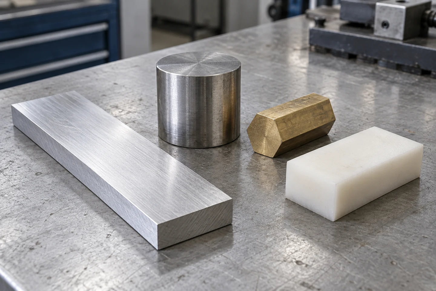
“6061 aluminum” identifies the alloy. The temper describes its processing condition; the product standard and stock form complete the purchasing requirement. Plate and extruded bar can have different size ranges and property requirements.
T651 includes stress relief by stretching. It is not an interchangeable label for T6: the applicable product specification and approval requirements still govern any substitution.
7075-T6 and 7075-T73
Kaiser’s 7075 data distinguish the higher typical strength of T6/T651 from the improved stress-corrosion resistance of T73/T7351. The choice depends on loading and environment. A temper change can improve one property while reducing another, so it needs design approval.
The 7075 sheet, coil and plate data sheet covers a different product family from rod and bar. The material actually purchased needs the applicable specification and batch records; a brochure and a material certificate serve different purposes.
For a pocketed enclosure, start at the working faces
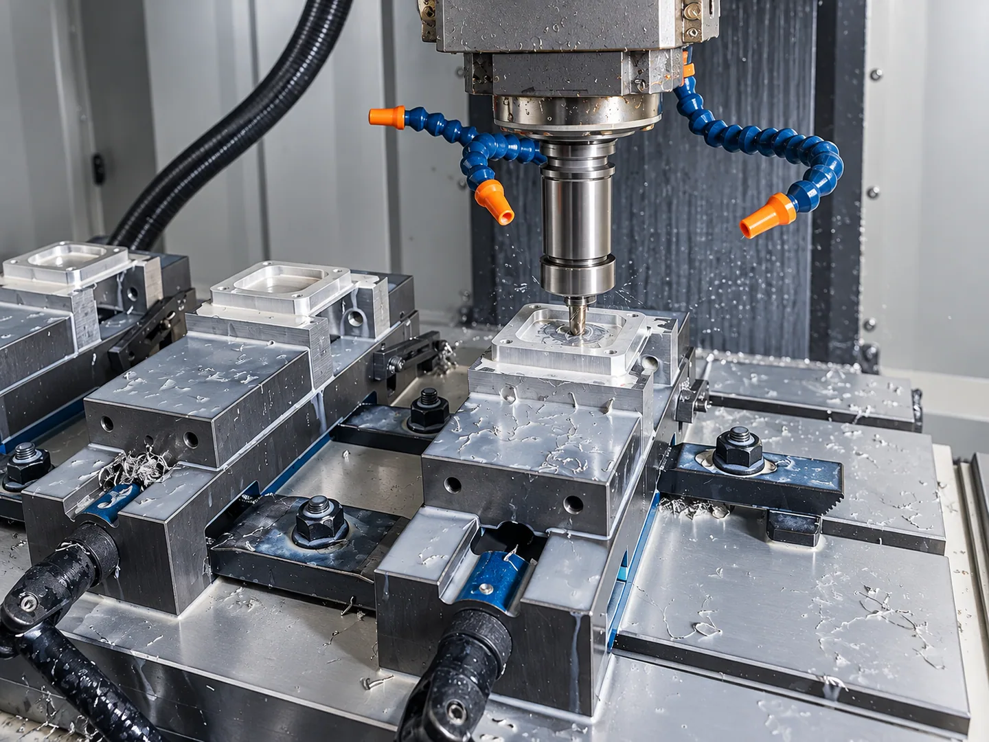
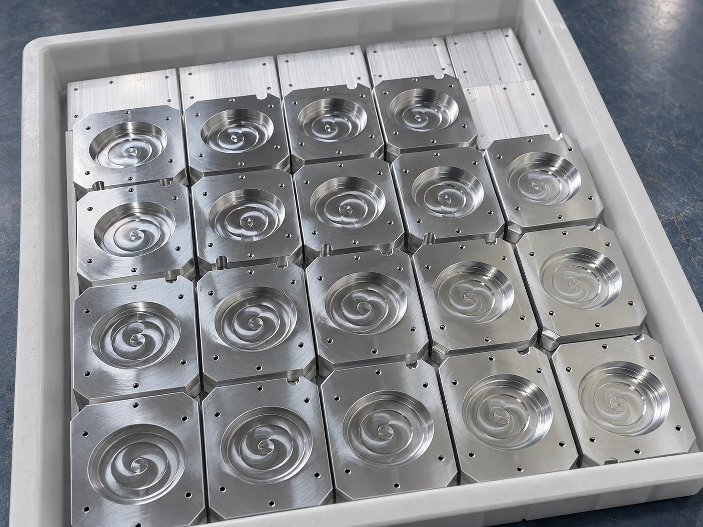
The pocketed enclosure study shows recesses, walls and mounting features. A new enclosure of this form needs a clear distinction between faces that locate or seal, a loaded wall, and a wall that mainly protects the contents.
A press fit, sliding fit and fastener-clearance bore require different limits. The load calculation supports a strength choice; span and support address wall movement. An appearance-led part needs a treatment and visual reference before material is ordered.
Opening the pockets changes how the component can be supported. Stock condition, workholding and the inspection state belong beside the alloy decision.
After choosing the grade and temper, review the enclosure’s wall support and pocket access. A stronger alloy still leaves the cutter with the same corner and reach constraints. The closure fit and any final surface treatment need to remain connected to the chosen geometry.
Follow the load through a bracket or bore
A stronger alloy becomes useful when the available section cannot meet the load requirement. The governing section may be a bore, fastener seat or thin ligament. Its outside dimensions alone do not establish the load path.
In the multi-feature part examples, faces and holes serve different assembly functions. A threaded joint also depends on thread size, engagement, mating material and assembly load; a pin joint may depend on bearing contact and fit.
Once the load and fit requirements are established, the drawing guide shows how to connect a feature callout to an inspection result.
A billet intake manifold adds another set of interface questions: flange alignment, internal passage access and the construction of any split joint. Material selection belongs with that component and assembly definition, together with any separately specified operating tests.
Exposure and joining can settle the choice
Moisture, cleaning fluids, trapped liquid and contact with dissimilar metals affect the assembly. A wet, continuously stressed connection needs a different assessment from a dry covered part. Protected and bare surfaces, as well as electrical continuity, can change the finishing requirements.
6061 is commonly used where corrosion resistance and welding matter. Welding can reduce T6 strength in the weld region, so the joint still needs its own design and qualification. Hydro’s Alloy 6061 technical sheet explains both the welding and corrosion considerations.
A welded 6061 design cannot simply inherit the same joining assumptions after a change to 7075. Conventional fusion welding requires a separate suitability assessment. Bolted joints instead need their fit, preload and corrosion requirements addressed.
Treat colour and final fit as separate requirements
Both alloys can be anodized. The alloy, preparation and process affect the result, so an appearance sample should use the specified material and intended treatment. A black colour reference does not establish a bore size or coating requirement.
Anodizing converts the surface to oxide and changes finished dimensions. The Aluminum Anodizers Council FAQ explains that alloy and process affect growth, and gives different nominal relationships for Type II and hardcoat anodizing. The actual finishing process determines the machining allowance.
Carry the final dimensions through finishing
For an anodized part, the drawing needs to say whether a bore limit applies before or after treatment. Masked bores, threads and contact faces should be identifiable. The material and surface-treatment guide follows the effect on fits.
Distortion also depends on stock and workholding
Thin walls and asymmetric pockets need a sequence suited to the stock condition and material removal. Stress-relieved stock is one part of that assessment; geometry, support and the order of operations still matter.
The two-operation milling example introduces the locating questions for a part that needs repositioning. Dimensions made in different setups must remain related after release from the fixture.
Flatness or shape acceptance needs a stated condition: free, under a specified restraint, or after an agreed treatment. The quoted route and any approved change should retain that finished tolerance and measurement condition.
Compare complete finished parts
Compare prices for the same finished requirements, quantity and records. Stock form, machining allowance, setups, finishing and inspection can outweigh a small difference in finished weight.
Where both alloys suit the design, separate quotations against the same drawing show the cost difference. If a material change needs new geometry, compare the complete designs. The CNC machining cost guide explains the other work behind the price.
A proposed substitute remains an alternative until approved. The released material and condition then carry through sample approval and repeat orders.
Bring the open material decision to the inquiry
| Record | Useful information |
|---|---|
| Function and loads | Loaded section, required strength, permitted deflection and assembly interfaces. |
| Material | Alloy, temper, product standard, stock form and required condition. |
| Environment and joining | Exposure, operating temperature, mating materials and joining process. |
| Finish | Treatment, appearance reference, masking and dimensions after treatment. |
| Files and records | Current drawing/model revision, material traceability and inspection records. |
| Quantity and alternatives | Initial and repeat quantities, with substitutions identified for approval. |
An inquiry can start before every material choice is settled. The known loads, interfaces and environment give us a basis for discussing machining and quotation scope; the responsible designer approves the final alloy or substitution.
LZZ’s aluminum options include 6061, 7075 and 2024. The aluminum machining page covers the material and drawing information for a new part.
Questions about choosing an alloy
Does choosing 7075 buy a tighter tolerance?
No. A tolerance must be specified for the feature; the alloy name alone does not establish it. Geometry, stock condition, workholding, machining sequence, treatment and measurement determine how that requirement can be met.
What does a material certificate establish?
It identifies the supplied material and the stated results or compliance scope. It does not approve the part geometry, establish assembly strength or replace dimensional acceptance.
Can I compare alloys before releasing the drawing?
Yes. A current model and drawing, the quantities under consideration, and the requirement driving the comparison are a useful starting point. Any quotation assumptions remain separate from the production specification until approved.
Carry the material choice onto the drawing
The EX-MOUNT-01 teaching plate uses 6061-T6 as an example specification. Its bore, hole spacing and thickness connect drawing callouts to an illustrative inspection sheet. This is a teaching example, not a load-verified material selection or production record.
See the annotated drawing, feature checks and inspection results, including the thickness result that pauses release. The SVG drawing and CSV sheet are available with the full example.